Fluke 1625 FE 1625 Users Manual - Page 15
Assembly, Description of Functions, Earth/Ground Tester.
 |
View all Fluke 1625 manuals
Add to My Manuals
Save this manual to your list of manuals |
Page 15 highlights
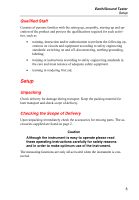
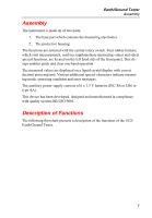
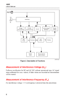
Earth/Ground Tester Assembly Assembly The instrument is made up of two parts: 1. The base part which contains the measuring electronics. 2. The protective housing. The functions are selected with the central rotary switch. Four rubber buttons, which start measurements, read out supplementary measuring values and select special functions, are located on the left hand side of the front panel. This design enables quick and clear one-hand operation. The measured values are displayed on a liquid crystal display with correct decimal point and unit. Various additional special characters indicate measuring mode, operating condition and error messages. The auxiliary power supply consists of 6 x 1.5 V batteries (IEC R6 or LR6 or type AA). This device has been developed, designed and manufactured in compliance with quality system DIN ISO 9001. Description of Functions The following flowchart presents a description of the functions of the 1625 Earth/Ground Tester. 7
-
 1
1 -
2
-
3
-
4
-
5
-
6
-
7
-
8
-
9
-
 10
10 -
 11
11 -
 12
12 -
 13
13 -
 14
14 -
 15
15 -
 16
16 -
 17
17 -
 18
18 -
 19
19 -
 20
20 -
21
-
22
-
23
-
24
-
25
-
26
-
27
-
28
-
29
-
30
-
31
-
32
-
33
-
34
-
35
-
36
-
37
-
38
-
39
-
40
-
41
-
42
-
43
-
44
-
45
-
46
-
47
-
48
-
49
-
50
-
51
-
52
-
53
-
54
-
55
-
56
-
57
-
58
-
59
-
60
-
61
-
62
-
63
-
64
-
65
-
66
-
67
-
68
-
69
-
70
-
71
-
72
-
73
-
74
-
75
-
76
-
77
-
78
-
79
-
80
-
81
-
82
-
83
-
84
-
85
-
86
-
87
-
88
-
89
-
90
 |
 |
