Fluke 1625 FE 1625 Users Manual - Page 17
Measurement of Earthing Resistance (RE), Resistance Measurement (R~) - tester
 |
View all Fluke 1625 manuals
Add to My Manuals
Save this manual to your list of manuals |
Page 17 highlights
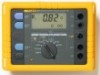
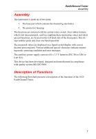
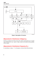
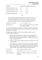
Earth/Ground Tester Description of Functions Measurement of Earthing Resistance (RE) The earthing resistance is determined by a 3- or 4-pole current and voltage measurement. The measuring voltage is a square pulse AC voltage with 48 / 20 V and a frequency of 94, 105, 111 or 128 Hz. The frequency can be selected manually or automatically (AFC). Selective Measurement of Earthing Resistance (RE A) Measurement of a single earth electrode in a mesh operated (parallel) earthing system. The current flowing through the single earth electrode is measured with an external current transformer. Resistance Measurement (R~) The resistance is determined by a 2 pole current and voltage measurement. The measuring voltage is a square pulse AC voltage with 20 V and a frequency of 94, 105, 111 or 128 Hz. The frequency can be selected manually or automatically (AFC). Low Resistance Measurement (RF) The resistance is determined by DC current and voltage measurement. 2- as well as 4-pole measurement is possible. The short circuit current is > 200 mA. The resistance of both current directions is measured and stored. Checking for Correct Measuring Connection The processor checks if the measuring lead is properly connected according to the selected function via isolated, two piece contacts, inside of each 4 mm (banana) input socket, in combination with detection circuitry. A wrong or missing connection is indicated by an optical or acoustical signal. Beeper The built in beeper has two functions: 1. Giving messages if set limit values are exceeded. 2. Indicating dangerous conditions or maloperation. Controlling is done by means of the microprocessor. 9
-
 1
1 -
2
-
3
-
4
-
5
-
6
-
7
-
8
-
9
-
10
-
11
-
 12
12 -
 13
13 -
 14
14 -
 15
15 -
 16
16 -
 17
17 -
 18
18 -
 19
19 -
 20
20 -
 21
21 -
 22
22 -
23
-
24
-
25
-
26
-
27
-
28
-
29
-
30
-
31
-
32
-
33
-
34
-
35
-
36
-
37
-
38
-
39
-
40
-
41
-
42
-
43
-
44
-
45
-
46
-
47
-
48
-
49
-
50
-
51
-
52
-
53
-
54
-
55
-
56
-
57
-
58
-
59
-
60
-
61
-
62
-
63
-
64
-
65
-
66
-
67
-
68
-
69
-
70
-
71
-
72
-
73
-
74
-
75
-
76
-
77
-
78
-
79
-
80
-
81
-
82
-
83
-
84
-
85
-
86
-
87
-
88
-
89
-
90
 |
 |