Fluke 1625 FE 1625 Users Manual - Page 22
Table 2. Electrical Measurement Specifications, Reference Con
 |
View all Fluke 1625 manuals
Add to My Manuals
Save this manual to your list of manuals |
Page 22 highlights
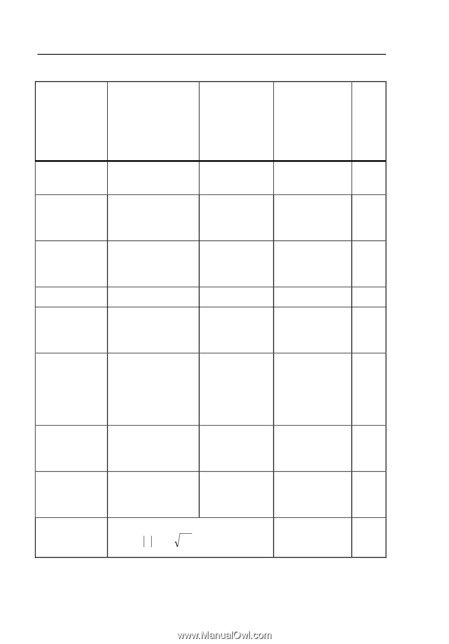
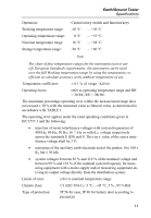
1625 Users Manual Table 2. Electrical Measurement Specifications Intrinsic Error or Influence Quan- tity Reference Conditions or Speci- fied Operating Range Designation Code Requirements or Test in Accordance with the Relevant Parts of IEC 1557 Type of Test Intrinsic error Reference condi- A tions Part 5, 6.1 R Position Reference posi- E1 tion ± 90° Part 1, 4.2 R Supply volt- At the limits E2 age stated by the manufacturer Part 1, 4.2, R 4.3 Temperature 0 °C and 35 °C E3 Part 1, 4.2 T Series inter- See 4.2 and 4.3 E4 ference voltage Part 5, 4.2, T 4.3 Resistance 0 to 100 x RA E5 of the probes and auxiliary but ≤ 50 kΩ earth elec- trodes Part 5, 4.3 T System frequency 99 % to 101 % of E7 the nominal frequency Part 5, 4.3 T System volt- 85 % to 110 % of E8 age the nominal volt- age Part 5, 4.3 T Operating Part 5, 4.3 R error B = ±( A + 1,15 E12 E22 E32 E 2 4 E52 E62 E72 E82 14
-
 1
1 -
2
-
3
-
4
-
5
-
6
-
7
-
8
-
9
-
10
-
11
-
12
-
13
-
14
-
15
-
16
-
 17
17 -
 18
18 -
 19
19 -
 20
20 -
 21
21 -
 22
22 -
 23
23 -
 24
24 -
 25
25 -
 26
26 -
 27
27 -
28
-
29
-
30
-
31
-
32
-
33
-
34
-
35
-
36
-
37
-
38
-
39
-
40
-
41
-
42
-
43
-
44
-
45
-
46
-
47
-
48
-
49
-
50
-
51
-
52
-
53
-
54
-
55
-
56
-
57
-
58
-
59
-
60
-
61
-
62
-
63
-
64
-
65
-
66
-
67
-
68
-
69
-
70
-
71
-
72
-
73
-
74
-
75
-
76
-
77
-
78
-
79
-
80
-
81
-
82
-
83
-
84
-
85
-
86
-
87
-
88
-
89
-
90
 |
 |