Fluke 1625 FE 1625 Users Manual - Page 45
-pole/4-pole Measurement of Single Earth Electrode Resistances
 |
View all Fluke 1625 manuals
Add to My Manuals
Save this manual to your list of manuals |
Page 45 highlights
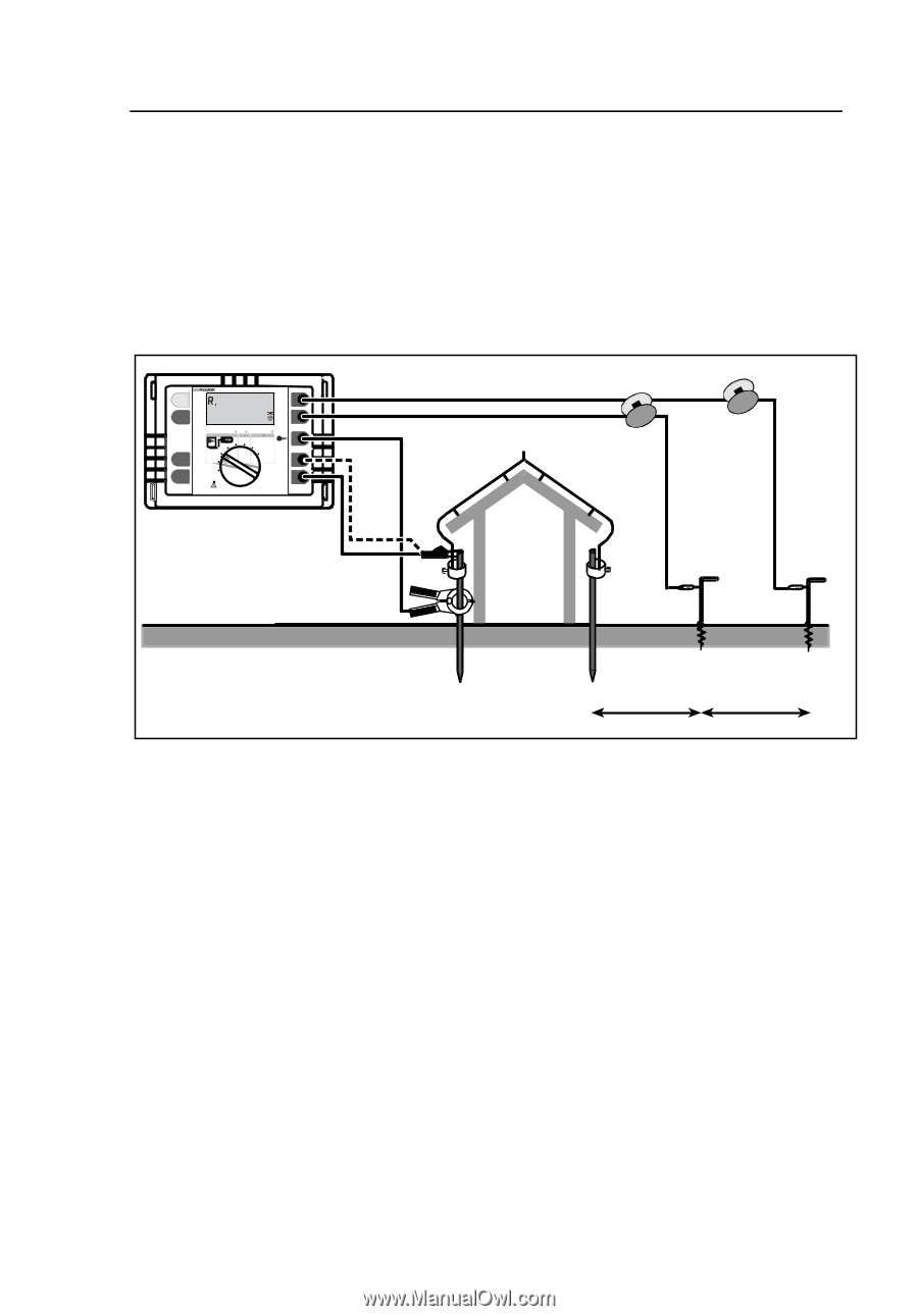
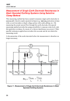
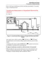
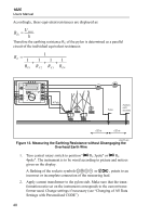
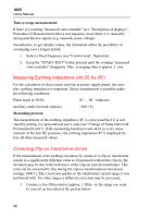
Earth/Ground Tester Procedure of Measurements Errors of the current transformer can be corrected as described in "Correcting Clip-on Transformer Error". 3-pole/4-pole Measurement of Single Earth Electrode Resistances See Figure 12. START TEST 1625 EARTH / GROUND TESTER H /C2 DISPLAY MENU Earth/Ground Resistance 300 k RA AC Resistance 300 k R DC Low Resistance 3k R 4 POLE 3 POLE 2 POLE 2 POLE CHANGE ITEM 4 POLE 3 POLE 4 POLE SELECT OFF S/P2 ES/P1 E /C1 4 Pole Probe Auxiliary earth electrode Earth electrode >20 m >20 m edw015.eps Figure 12. 3-pole/4-pole Measurement of Single Earth Electrode Resistances Turn central rotary switch to position "A RE 3pole" or "A RE 4pole". The instrument is to be wired according to picture and notices given on the display. A flashing of the sockets symbols EFGH or A, points to an incorrect or incomplete connection of the measuring lead. Fix clip-on transformer around the earth electrode to be measured. Make sure that the clip-on transformation ratio set on the instrument corresponds to the clip-on transformer used. Change settings if necessary (see "Changing of all Data Settings with Personalised CODE") 37
-
 1
1 -
2
-
3
-
4
-
5
-
6
-
7
-
8
-
9
-
10
-
11
-
12
-
13
-
14
-
15
-
16
-
17
-
18
-
19
-
20
-
21
-
22
-
23
-
24
-
25
-
26
-
27
-
28
-
29
-
30
-
31
-
32
-
33
-
34
-
35
-
36
-
37
-
38
-
39
-
 40
40 -
 41
41 -
 42
42 -
 43
43 -
 44
44 -
 45
45 -
 46
46 -
 47
47 -
 48
48 -
 49
49 -
 50
50 -
51
-
52
-
53
-
54
-
55
-
56
-
57
-
58
-
59
-
60
-
61
-
62
-
63
-
64
-
65
-
66
-
67
-
68
-
69
-
70
-
71
-
72
-
73
-
74
-
75
-
76
-
77
-
78
-
79
-
80
-
81
-
82
-
83
-
84
-
85
-
86
-
87
-
88
-
89
-
90
 |
 |