Fluke 1625 FE 1625 Users Manual - Page 49
Notices for the setting of earth spikes, If the displayed R
 |
View all Fluke 1625 manuals
Add to My Manuals
Save this manual to your list of manuals |
Page 49 highlights
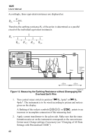
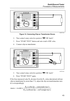
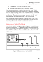
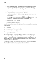
Earth/Ground Tester Procedure of Measurements 3. Press "START TEST" button Now a fully automated test sequence of all relevant parameters like auxiliary earth electrode, probe- and earth electrode resistance, is implemented and finishes with the display of the result RE. 4. Read out measured value RE 5. Call RS and RH with "DISPLAY MENU". Notices for the setting of earth spikes: Before setting the earth spikes for probe and auxiliary earth electrode make sure that the probe is set outside the potential gradient of earth electrode and auxiliary earth electrode (see also "The Influence of Potential Gradient Areas on Earth Resistance Measurement"). Such a condition is normally reached by allowing a distance of >20 m between the earth electrode and the earth spikes as well as to the earth spikes to each other. An accuracy test of the results is made with another measurement after repositioning of auxiliary earth electrode or probe. If the result is the same, the distance is sufficient. If the measured value changes, probe or auxiliary earth electrode must be repositioned until the measured value RE remains constant. Spike wires should not run too close. 1. Apply current transformer to next pylon stub. 2. Repeat measuring sequence. Current feeding point of measuring current (alligator clip) and the polarity of the split core current transformer has to be left unchanged. After values of REi of all pylon foots are determined, the actual earth resistance RE has to be calculated: RE = 1 + 1 1 + 1 + 1 RE1 R E2 RE3 RE4 Note If the displayed RE value is negative despite correct orientation of the current transformer, a part of the measuring current is flowing upwards into the tower body. The earthing resistance, thus coming into effect, correctly calculates, if the individual equivalent resistances (under observation of their polarity) are inserted into the equation above. 41
-
 1
1 -
2
-
3
-
4
-
5
-
6
-
7
-
8
-
9
-
10
-
11
-
12
-
13
-
14
-
15
-
16
-
17
-
18
-
19
-
20
-
21
-
22
-
23
-
24
-
25
-
26
-
27
-
28
-
29
-
30
-
31
-
32
-
33
-
34
-
35
-
36
-
37
-
38
-
39
-
40
-
41
-
42
-
43
-
 44
44 -
 45
45 -
 46
46 -
 47
47 -
 48
48 -
 49
49 -
 50
50 -
 51
51 -
 52
52 -
 53
53 -
 54
54 -
55
-
56
-
57
-
58
-
59
-
60
-
61
-
62
-
63
-
64
-
65
-
66
-
67
-
68
-
69
-
70
-
71
-
72
-
73
-
74
-
75
-
76
-
77
-
78
-
79
-
80
-
81
-
82
-
83
-
84
-
85
-
86
-
87
-
88
-
89
-
90
 |
 |