Fluke 1625 FE 1625 Users Manual - Page 53
Measurement of Soil Resistivity
 |
View all Fluke 1625 manuals
Add to My Manuals
Save this manual to your list of manuals |
Page 53 highlights
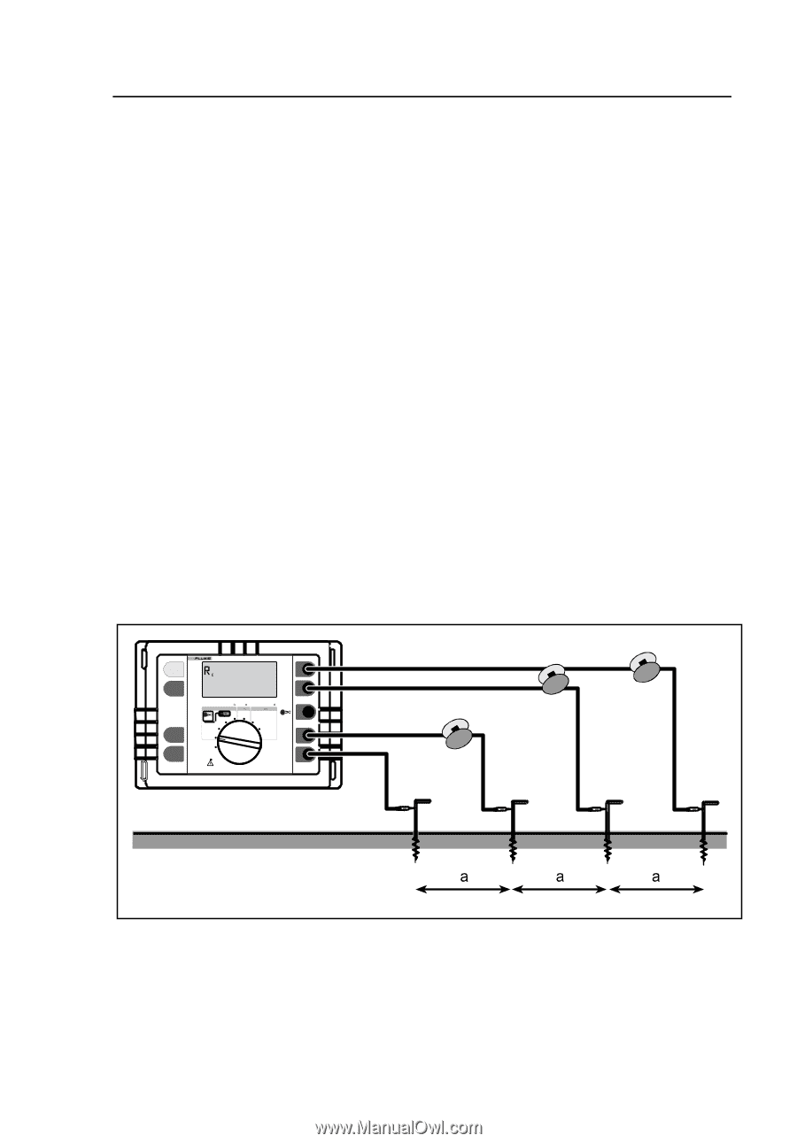
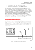
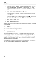
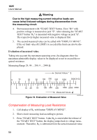
Earth/Ground Tester Procedure of Measurements 3. Call display RK with "DISPLAY MENU" button. 4. Implement compensation with "START TEST" button. The compensation resistance is displayed only for as long as the "START TEST" button is kept pressed. After releasing the "START TEST" button the measured value is stored and the measuring instrument returns to the standard settings at the beginning of the measurement so that a succeeding measurement of the earthing resistance can be implemented by pressing "START TEST" again. Thereafter, RK is subtracted from the actual measured value. If the compensation value has to be reset to the basic setting (0.000 Ω), the compensation sequence has to be implemented with an open (disconnected) measuring lead or turn the switch to the next position and back. Measurement of Soil Resistivity The soil resistivity is the geological and physical quantity for calculation and design of earthing systems. The measuring procedure applied below uses the method developed by Wenner (F.Wenner, A method of measuring earth resistivity; Bull. National Bureau of Standards, Bulletin 12 (4), Paper 258, S 478496; 1915/16). START TEST 1625 EARTH / GROUND TESTER H /C2 DISPLAY MENU Earth/Ground Resistance 300 k RA AC Resistance 300 k R DC Low Resistance 3k R 4 POLE 3 POLE 2 POLE 2 POLE CHANGE ITEM 4 POLE 3 POLE 4 POLE SELECT OFF S/P2 ES/P1 E /C1 Figure 16. Measurement of Soil Resistivity edw020.eps 45
-
 1
1 -
2
-
3
-
4
-
5
-
6
-
7
-
8
-
9
-
10
-
11
-
12
-
13
-
14
-
15
-
16
-
17
-
18
-
19
-
20
-
21
-
22
-
23
-
24
-
25
-
26
-
27
-
28
-
29
-
30
-
31
-
32
-
33
-
34
-
35
-
36
-
37
-
38
-
39
-
40
-
41
-
42
-
43
-
44
-
45
-
46
-
47
-
 48
48 -
 49
49 -
 50
50 -
 51
51 -
 52
52 -
 53
53 -
 54
54 -
 55
55 -
 56
56 -
 57
57 -
 58
58 -
59
-
60
-
61
-
62
-
63
-
64
-
65
-
66
-
67
-
68
-
69
-
70
-
71
-
72
-
73
-
74
-
75
-
76
-
77
-
78
-
79
-
80
-
81
-
82
-
83
-
84
-
85
-
86
-
87
-
88
-
89
-
90
 |
 |