Fluke 1625 FE 1625 Users Manual - Page 54
Fluke 1625 Manual
 |
View all Fluke 1625 manuals
Add to My Manuals
Save this manual to your list of manuals |
Page 54 highlights
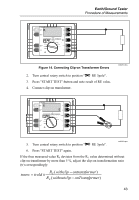
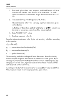
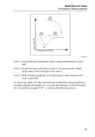
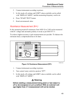
1625 Users Manual 1. Four earth spikes of the same length are positioned into the soil in an even line and with the same distance "a" to each other. The earth spikes should not be hammered in deeper than a maximum of 1/3 of "a". 2. Turn central rotary switch to position "RE 4pole". The instrument is to be wired according to picture and notices given on the display. A flashing of the sockets symbols EFGH or B, points to an incorrect or incomplete connection of the measuring lead. 3. Push "START TEST" button. 4. Read out measured value RE. From the indicated resistance value RE, the soil resistivity calculates according to the equation: ρ E = 2π .a.RE ρE ...... mean value of soil resistivity (Ωm) RE ...... measured resistance (Ω) a ...... probe distance (m) The measuring method according to Wenner determines the soil resistivity down to a depth of approx. the distance "a" between two earth spikes. By increasing "a", deeper strata can be measured and checked for homogenity. By changing "a" several times, a profile can be measured from which a suitable earth electrode can be determined. According to the depth to be measured, "a" is selected between 2 m and 30 m. This procedure results in curves depicted in the graph below. 46
-
 1
1 -
2
-
3
-
4
-
5
-
6
-
7
-
8
-
9
-
10
-
11
-
12
-
13
-
14
-
15
-
16
-
17
-
18
-
19
-
20
-
21
-
22
-
23
-
24
-
25
-
26
-
27
-
28
-
29
-
30
-
31
-
32
-
33
-
34
-
35
-
36
-
37
-
38
-
39
-
40
-
41
-
42
-
43
-
44
-
45
-
46
-
47
-
48
-
 49
49 -
 50
50 -
 51
51 -
 52
52 -
 53
53 -
 54
54 -
 55
55 -
 56
56 -
 57
57 -
 58
58 -
 59
59 -
60
-
61
-
62
-
63
-
64
-
65
-
66
-
67
-
68
-
69
-
70
-
71
-
72
-
73
-
74
-
75
-
76
-
77
-
78
-
79
-
80
-
81
-
82
-
83
-
84
-
85
-
86
-
87
-
88
-
89
-
90
 |
 |