Fluke 1625 FE 1625 Users Manual - Page 58
Compensation of Measuring Lead Resistance, Due to the high measuring current inductive loads can
 |
View all Fluke 1625 manuals
Add to My Manuals
Save this manual to your list of manuals |
Page 58 highlights
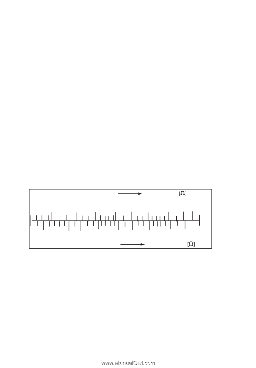
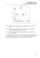
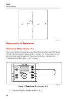
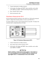
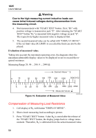
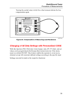
1625 Users Manual W Warning Due to the high measuring current inductive loads can cause lethal induced voltages during disconnection from the measuring circuit. 4. Start measurement with "START TEST" button. First, "R1" with positive voltage is measured on jack "E". After releasing the "START TEST" button "R2" is measured with negative voltage on jack "E". The respectively higher measured value is displayed first. 5. The second measured value can be called with "DISPLAY MENU". If the set limit value (R LIMIT) is exceeded the limit can also be displayed. Evaluation of measured value: Taking into account the maximum operating error, the diagrams show the maximum admissable display values to be displayed so not to exceed the required resistance. Measuring Range 29, 99 ... 299, 9 ... 2999 Ω 0 10 Desired Values 20 50 100 200 500 1000 3000 3152 5 10 20 50 100 200 500 1000 2000 2999 Measured Values Figure 19. Evaluation of Measured Value edw025.eps Compensation of Measuring Lead Resistance 1. Call display of RK with button "DISPLAY MENU". 2. Short circuit measuring lead according to picture. 3. Press "START TEST" button. Value RK is stored after the release of the "START TEST" button, the display jumps back to voltage measurement. Thereafter, RK is subtracted from the actual measured value. 50
-
 1
1 -
2
-
3
-
4
-
5
-
6
-
7
-
8
-
9
-
10
-
11
-
12
-
13
-
14
-
15
-
16
-
17
-
18
-
19
-
20
-
21
-
22
-
23
-
24
-
25
-
26
-
27
-
28
-
29
-
30
-
31
-
32
-
33
-
34
-
35
-
36
-
37
-
38
-
39
-
40
-
41
-
42
-
43
-
44
-
45
-
46
-
47
-
48
-
49
-
50
-
51
-
52
-
 53
53 -
 54
54 -
 55
55 -
 56
56 -
 57
57 -
 58
58 -
 59
59 -
 60
60 -
 61
61 -
 62
62 -
 63
63 -
64
-
65
-
66
-
67
-
68
-
69
-
70
-
71
-
72
-
73
-
74
-
75
-
76
-
77
-
78
-
79
-
80
-
81
-
82
-
83
-
84
-
85
-
86
-
87
-
88
-
89
-
90
 |
 |