Fluke 1625 FE 1625 Users Manual - Page 76
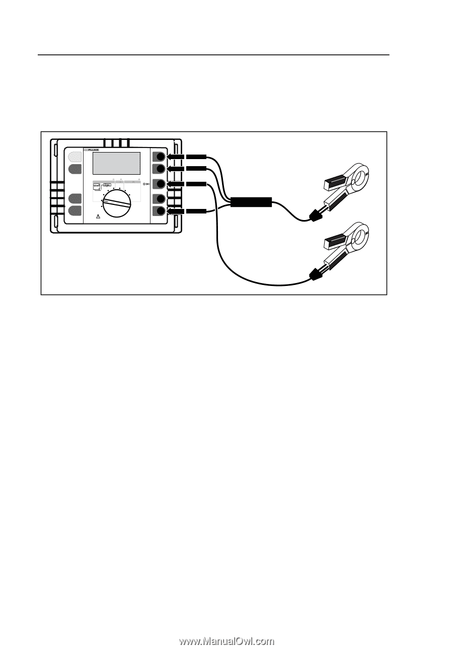
Operation, Clamp both transformers around the ground conductor to be tested.
 |
View all Fluke 1625 manuals
Add to My Manuals
Save this manual to your list of manuals |
Page 76 highlights
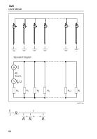
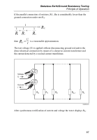
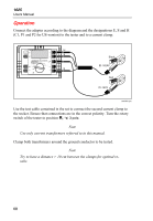
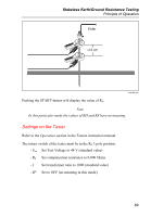
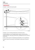
1625 Users Manual Operation Connect the adapter according to the diagram and the designations E, S and H (C1, P1 and P2 for US-version) to the tester and to a current clamp. START TEST 1625 EARTH / GROUND TESTER H /C2 DISPLAY MENU Earth/Ground Resistance 300 k RA CHANGE ITEM 4 POLE 3 POLE 4 POLE 3 POLE AC Resistance 300 k R DC Low Resistance 3k R 2 POLE 2 POLE 4 POLE SELECT OFF S/P2 ES/P1 E /C1 H S E Black EI-162AC Red EI-162X edw063.eps Use the test cable contained in the set to connect the second current clamp to the socket. Ensure that connections are in the correct polarity. Turn the rotary switch of the tester to position RE D 3 pole. Note Use only current transformers referred to in this manual. Clamp both transformers around the ground conductor to be tested. Note Try to have a distance > 10 cm between the clamps for optimal results. 68
-
 1
1 -
2
-
3
-
4
-
5
-
6
-
7
-
8
-
9
-
10
-
11
-
12
-
13
-
14
-
15
-
16
-
17
-
18
-
19
-
20
-
21
-
22
-
23
-
24
-
25
-
26
-
27
-
28
-
29
-
30
-
31
-
32
-
33
-
34
-
35
-
36
-
37
-
38
-
39
-
40
-
41
-
42
-
43
-
44
-
45
-
46
-
47
-
48
-
49
-
50
-
51
-
52
-
53
-
54
-
55
-
56
-
57
-
58
-
59
-
60
-
61
-
62
-
63
-
64
-
65
-
66
-
67
-
68
-
69
-
70
-
 71
71 -
 72
72 -
 73
73 -
 74
74 -
 75
75 -
 76
76 -
 77
77 -
 78
78 -
 79
79 -
 80
80 -
 81
81 -
82
-
83
-
84
-
85
-
86
-
87
-
88
-
89
-
90
 |
 |