Fluke 1625 FE 1625 Users Manual - Page 82
B. Earthing Resistance, Introduction, Appendix B
 |
View all Fluke 1625 manuals
Add to My Manuals
Save this manual to your list of manuals |
Page 82 highlights
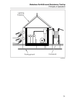
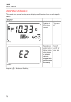
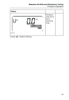
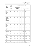
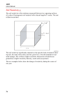
Appendix B Earthing Resistance Introduction Per definition, the earthing resistance consists of several individual resistances. 1. The resistance of connecting lead to earth electrode 2. The resistance of the actual earth electrode; earthing rod, earthing plate, earthing strip, mesh earth electrode etc. 3. The dissipation resistance, the resistance between earth electrode and soil potential. As the connecting cable and the resistance of the earth electrode are negligibly small after correct dimensioning, the earthing resistance dominantly dependends on the dissipation resistance. This shows that an accurate measurement of the dissipation resistance is necessary to determine the exact earthing conditions for protective measures. As the dissipation resistance is not only dependent on the specific soil resistivity, that is the resistance of the actual soil ( gravel, clay, granite ), but also significantly depents on the shape of the earth electrode, a metrological check has to be made even if the position of the earth electrode and the condition of the soil is well known. For redimensioning of an earthing system, e.g. a lightning protection, an approximate calculation, according to the table below, is possible. As a basis for this calculation the soil resistivity of the spot where the earth electrode is to be installed has to be known. 74
-
 1
1 -
2
-
3
-
4
-
5
-
6
-
7
-
8
-
9
-
10
-
11
-
12
-
13
-
14
-
15
-
16
-
17
-
18
-
19
-
20
-
21
-
22
-
23
-
24
-
25
-
26
-
27
-
28
-
29
-
30
-
31
-
32
-
33
-
34
-
35
-
36
-
37
-
38
-
39
-
40
-
41
-
42
-
43
-
44
-
45
-
46
-
47
-
48
-
49
-
50
-
51
-
52
-
53
-
54
-
55
-
56
-
57
-
58
-
59
-
60
-
61
-
62
-
63
-
64
-
65
-
66
-
67
-
68
-
69
-
70
-
71
-
72
-
73
-
74
-
75
-
76
-
 77
77 -
 78
78 -
 79
79 -
 80
80 -
 81
81 -
 82
82 -
 83
83 -
 84
84 -
 85
85 -
 86
86 -
 87
87 -
88
-
89
-
90
 |
 |