Fluke 1625 FE 1625 Users Manual - Page 86
Measuring Method, U
 |
View all Fluke 1625 manuals
Add to My Manuals
Save this manual to your list of manuals |
Page 86 highlights
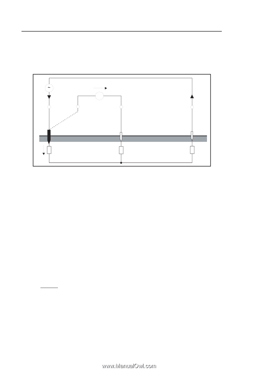
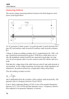
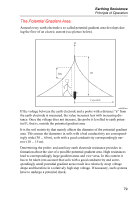
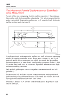
1625 Users Manual Measuring Method The current voltage measuring method is based on the block diagram circuit shown in the figure below. G U meas. I V E ES S I H E S H RE RS RH UE edw057.eps An AC generator G feeds current I via earth electrode E (earth electrode resistance RE) and auxiliary earth electrode H (auxiliary earth electrode resistance RH). Voltage UE drops on earthing resistance RE (UE proportional to RE.) This voltage is picked up and measured by probe S. With the so called three wire circuit, the instrument sockets E and ES are connected to each other. In a four wire circuit an separate cable is used to connect socket ES with the earth electrode. With that, the voltage drop of the cable between socket E and earth electrode is not measured. As the voltage measuring circuit has such a high impedance, the influence by the probe resistance RS is neglectable within certain limits. Thus the earthing resistance evolves RE = U Meas 1 and is independent from the resistance of the auxiliary earth electrode RH. The generator runs at a frequency between 70 and 140 Hz. It has to hold a minimum distance of 5 Hz to one of the nominal frequencies between 16 2/3, 50 or 60 Hz and their harmonic waves. A frequency selective filter adjusted to the generator frequency is inserted. 78
-
 1
1 -
2
-
3
-
4
-
5
-
6
-
7
-
8
-
9
-
10
-
11
-
12
-
13
-
14
-
15
-
16
-
17
-
18
-
19
-
20
-
21
-
22
-
23
-
24
-
25
-
26
-
27
-
28
-
29
-
30
-
31
-
32
-
33
-
34
-
35
-
36
-
37
-
38
-
39
-
40
-
41
-
42
-
43
-
44
-
45
-
46
-
47
-
48
-
49
-
50
-
51
-
52
-
53
-
54
-
55
-
56
-
57
-
58
-
59
-
60
-
61
-
62
-
63
-
64
-
65
-
66
-
67
-
68
-
69
-
70
-
71
-
72
-
73
-
74
-
75
-
76
-
77
-
78
-
79
-
80
-
 81
81 -
 82
82 -
 83
83 -
 84
84 -
 85
85 -
 86
86 -
 87
87 -
 88
88 -
 89
89 -
 90
90
 |
 |