Fluke 1625 FE 1625 Users Manual - Page 87
The Potential Gradient Area
 |
View all Fluke 1625 manuals
Add to My Manuals
Save this manual to your list of manuals |
Page 87 highlights
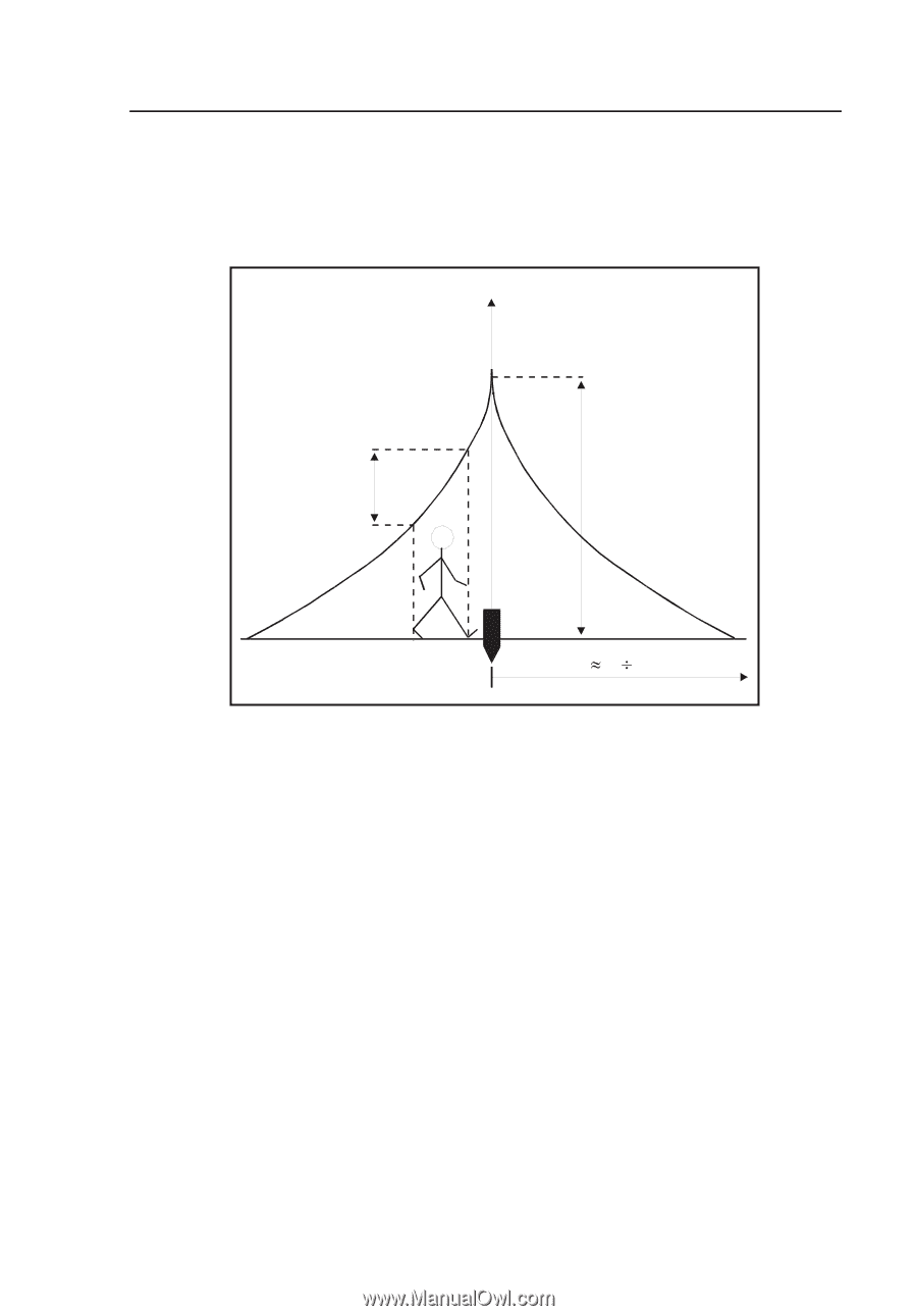
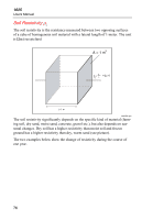
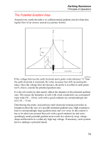
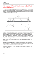
Earthing Resistance Principle of Operation The Potential Gradient Area Around every earth electrode a so called potential gradient area develops during the flow of an electric current (see picture below). U US UE E 40 60 m edw058.eps If the voltage between the earth electrode and a probe with a distance "a" from the earth electrode is measured, the value increases less with increasing distance. Once the voltage does not increase, the probe is levelled to earth potential FE that is, outside the potential gradient area. It is the soil resistivity that mainly affects the diameter of the potential gradient area. This means the diameters in soils with a bad conductivity are correspondingly wide (30 ... 60 m), soils with a good conductivity correspondingly narrow (10 ... 15 m). Determining the probe- and auxiliary earth electrode resistance provides information about the size of a possible potential gradient area. High resistances lead to correspondingly large gradient areas and vice versa. In this context it has to be taken into account that soils with a good conductivity and correspondingly small potential gradient areas result in a relatively steep voltage shape and therefore in a relatively high step voltage. If necessary, such systems have to undergo a potential check. 79
-
 1
1 -
2
-
3
-
4
-
5
-
6
-
7
-
8
-
9
-
10
-
11
-
12
-
13
-
14
-
15
-
16
-
17
-
18
-
19
-
20
-
21
-
22
-
23
-
24
-
25
-
26
-
27
-
28
-
29
-
30
-
31
-
32
-
33
-
34
-
35
-
36
-
37
-
38
-
39
-
40
-
41
-
42
-
43
-
44
-
45
-
46
-
47
-
48
-
49
-
50
-
51
-
52
-
53
-
54
-
55
-
56
-
57
-
58
-
59
-
60
-
61
-
62
-
63
-
64
-
65
-
66
-
67
-
68
-
69
-
70
-
71
-
72
-
73
-
74
-
75
-
76
-
77
-
78
-
79
-
80
-
81
-
 82
82 -
 83
83 -
 84
84 -
 85
85 -
 86
86 -
 87
87 -
 88
88 -
 89
89 -
 90
90
 |
 |