Fluke 1625 FE 1625 Users Manual - Page 89
Earth Impedance R* on High Voltage Transmission Lines
 |
View all Fluke 1625 manuals
Add to My Manuals
Save this manual to your list of manuals |
Page 89 highlights
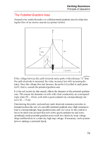
Earthing Resistance Principle of Operation Earth Impedance (R*) on High Voltage Transmission Lines The earthings of transmission line pylons are interconnected via the overhead earth wire. This wire is not only ohmic. There is also inductivity and resistivity (L´, R´). For calculation of the short circuit current this impedance at line frequency has to be determined. Inductivity and resistivity are known in most cases. Therefore the actual impedance can be calculated for each point of the line by a complex computation considering individual pylon resistance. This (computation) has to be done for each single pylon. The earth impedance can be measured with this instrument. The inductive portion of the impedance of the overhead wire is frequency dependent. Accordingly, the measuring frequency applied by the tester has to be close to the mains frequency in order to get correct readings. For that reason ordinary testers using frequencies between 70 Hz and 140 Hz show incorrect readings. This instrument measures with 55 Hz to be near enough to 50 / 60 Hz line frequency but to avoid interference with them 81
-
 1
1 -
2
-
3
-
4
-
5
-
6
-
7
-
8
-
9
-
10
-
11
-
12
-
13
-
14
-
15
-
16
-
17
-
18
-
19
-
20
-
21
-
22
-
23
-
24
-
25
-
26
-
27
-
28
-
29
-
30
-
31
-
32
-
33
-
34
-
35
-
36
-
37
-
38
-
39
-
40
-
41
-
42
-
43
-
44
-
45
-
46
-
47
-
48
-
49
-
50
-
51
-
52
-
53
-
54
-
55
-
56
-
57
-
58
-
59
-
60
-
61
-
62
-
63
-
64
-
65
-
66
-
67
-
68
-
69
-
70
-
71
-
72
-
73
-
74
-
75
-
76
-
77
-
78
-
79
-
80
-
81
-
82
-
83
-
 84
84 -
 85
85 -
 86
86 -
 87
87 -
 88
88 -
 89
89 -
 90
90
 |
 |