Fluke 1664FC US Product Manual
Fluke 1664FC US Manual
 |
View all Fluke 1664FC US manuals
Add to My Manuals
Save this manual to your list of manuals |
Fluke 1664FC US manual content summary:
- Fluke 1664FC US | Product Manual - Page 1
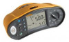
1662/1663/1664 FC Electrical Installation Tester Users Manual October 2015, Rev. 1, 4/16 © 2015-2016 Fluke Corporation. All rights reserved. Specifications are subject to change without notice. All product names are trademarks of their respective companies. MyFlukeStore Shop for Fluke products - Fluke 1664FC US | Product Manual - Page 2
and services are warranted for 90 days. This warranty extends only to the original buyer or end-user customer of a Fluke authorized Fluke. Warranty support is available only if product is purchased through a Fluke authorized sales outlet or Buyer has paid the applicable international price. Fluke - Fluke 1664FC US | Product Manual - Page 3
Table of Contents Title Page Introduction 1 How to Contact Fluke 1 Safety 2 Features and Accessories 5 Operation 8 Safety Features 8 Touch Pad 8 Live Circuit Detection 8 Earth Resistance Measurement 8 Safety Pretest 8 Mains Wiring Indicator 9 Quick Start 9 How to Use - Fluke 1664FC US | Product Manual - Page 4
1662/1663/1664 FC Users Manual Applications 57 How to Test a Mains Socket and Ring Installation 57 Earth Resistance Test by Loop Method 58 Zmax 59 Auto Start 60 Loop Impedance Test with 10 mA RCD 60 Auto Test Sequence (1664 FC 61 Memory Mode 63 Store a Measurement 65 Recall a Measurement - Fluke 1664FC US | Product Manual - Page 5
Terminal Settings 49 18. Earth Resistance Display/Dial and Terminal Settings 56 19. Auto Test Settings 62 20. Replacement Parts 69 iii MyFlukeStore Shop for Fluke products online at: www. .com 1.888.610.7664 - Fluke 1664FC US | Product Manual - Page 6
Resistance Loop Test (High-Current Trip Mode 59 15. Memory Mode 64 16. IR Serial Cable Attachment 67 17. Battery Replacement 72 v MyFlukeStore Shop for Fluke products online at: www. .com 1.888.610.7664 - Fluke 1664FC US | Product Manual - Page 7
Introduction The Fluke 166X Series (the Tester or Product) are battery-powered electrical installation testers. This manual applies to all 1662, 1663, and 1664 FC models. All figures show the Model 1664 FC. These Testers measure and test: • Voltage and Frequency • Insulation Resistance (EN61557-2) • - Fluke 1664FC US | Product Manual - Page 8
1664 FC Users Manual Safety See Table 1 for a list of symbols used on the Product and in this manual. A Warning identifies hazardous conditions and procedures that are dangerous to the user . • Carefully read all instructions. • Read all safety Fluke products online at: www. .com 1.888.610.7664 - Fluke 1664FC US | Product Manual - Page 9
or CAT IV environments without the protective cap installed. The protective cap decreases the possibility of arc flash caused by short circuits. 3 MyFlukeStore Shop for Fluke products online at: www. .com 1.888.610.7664 - Fluke 1664FC US | Product Manual - Page 10
1664 FC Users Manual Table 1. Symbols Symbol W X T Description WARNING. RISK OF DANGER. WARNING. HAZARDOUS VOLTAGE. Risk of electric shock. Consult user standards. Certified by TÜV SÜD Product Service. This product complies with the WEEE Fluke products online at: www. .com 1.888.610.7664 - Fluke 1664FC US | Product Manual - Page 11
probe Zero Adapter 1662 • • • • • • • • • • • • • • • 1663 1664 FC • • • • • • • • • • • • • • • • • • • • • • • • • • • • • • • • • • • • • • • • • • • • • • • • • • • • • • • 5 MyFlukeStore Shop for Fluke products online at: www. .com - Fluke 1664FC US | Product Manual - Page 12
1664 FC Users Manual The Product is delivered with the items listed in Table 3. If the Product is damaged or an item is missing, contact the place of purchase immediately. Table 3. Standard Accessories 1662 EU 1663/1664 FC EU 1662 UK 1663/1664 FC Fluke products online at: www. .com 1.888.610.7664 - Fluke 1664FC US | Product Manual - Page 13
Table 3. Standard Accessories (cont.) 1662 EU 1663/1664 FC EU 1662 UK 1663/1664 FC UK Description Part Number AC285-5001,175-276-013 Cap, and Tip Cover CD ROM, Users Manual Quick Reference Guide Tool Box (Hard Case with foam insert) Carrying Strap, Padded Fluke Zero Adapter • • 2041727 • • - Fluke 1664FC US | Product Manual - Page 14
1662/1663/1664 FC Users Manual Operation The Product is easy to use. The rotary dial clearly indicates the selected function. Push appliances from the test voltage. More information about Safety Pretest is on page 26. 8 MyFlukeStore Shop for Fluke products online at: www. .com 1.888.610.7664 - Fluke 1664FC US | Product Manual - Page 15
as you use the Tester. How to Use the Rotary Dial Use the rotary dial (see Table 5) to select the test type. 9 MyFlukeStore Shop for Fluke products online at: www. .com 1.888.610.7664 - Fluke 1664FC US | Product Manual - Page 16
1662/1663/1664 FC Users Manual 2 Table 5. Rotary Dial 3 4 1 5 6 10 9 7 8 Item Symbol V tripping time RCD tripping level Phase rotation Earth resistance (1663 and 1664 FC only) Auto Test (1664 FC only) 10 MyFlukeStore Shop for Fluke products online at: www. .com 1.888.610.7664 - Fluke 1664FC US | Product Manual - Page 17
.eps Push Button Description 1664 FC only - Turn on the radio for Fluke Connect. Press for >1 s to turn off the radio. Go to/exit Memory mode. Adjust function settings. See specific test instructions for more information. 11 MyFlukeStore Shop for Fluke products online at: www. .com - Fluke 1664FC US | Product Manual - Page 18
/1664 FC Users Manual No. Push Button A Table 6. Push Buttons (cont.) Description Use the up/down button to select features on the display. See specific test instructions measuring phase rotation. 12 MyFlukeStore Shop for Fluke products online at: www. .com 1.888.610.7664 - Fluke 1664FC US | Product Manual - Page 19
. See specific test instructions for more information. Illuminates only when the touch pad is touched to indicate that the PE input carries a high voltage (>100 V). Turns on when you press the Test button. Turns off when the test is complete. 13 MyFlukeStore Shop for Fluke products online at - Fluke 1664FC US | Product Manual - Page 20
1662/1663/1664 FC Users Manual Table 7. Display Features (cont.) Item Annunciator Definition Safety Pretest has detected a connected G + K More results are available. Use to scroll through the results. 14 MyFlukeStore Shop for Fluke products online at: www. .com 1.888.610.7664 - Fluke 1664FC US | Product Manual - Page 21
result or return a computed value based on the test result. See specific test instructions for more information. Measurement units for Secondary display. Memory locations. See Memory specified by local electrical codes. 15 MyFlukeStore Shop for Fluke products online at: www. .com 1.888.610.7664 - Fluke 1664FC US | Product Manual - Page 22
1662/1663/1664 FC Users Manual Item U V W X Y Z a Table 7. Display Features (cont.) Annunciator RCD 1664 FC is searching to connect. If it blinks at 5 s intervals, 1664 FC is connected to the Fluke Connect app. For more information about Fluke Connect, see page 68. 16 MyFlukeStore Shop for Fluke - Fluke 1664FC US | Product Manual - Page 23
Earth) N/L3/S (Neutral) hwl021f.eps The IR (infrared) port allows you to connect the Tester to a computer and download the test data with a Fluke PC software product. With the software, you can collect, organize, and display the test data in a format that meets your needs. See Download Test - Fluke 1664FC US | Product Manual - Page 24
1662/1663/1664 FC Users Manual Error Codes Various error conditions are detected by the Tester and are Self-Test Fails Over-Temp Code 1 2 apx032f.eps Solution Return the Tester to a Fluke Service Center. Secondary display shows additional code: 1: Unable to communicate with Analog board 2: Analog - Fluke 1664FC US | Product Manual - Page 25
memory is inconsistent. Download and save all data to a PC and clear all memory in the Tester. If the error persists, return the Tester to a Fluke Service Center. 19 MyFlukeStore Shop for Fluke products online at: www. .com 1.888.610.7664 - Fluke 1664FC US | Product Manual - Page 26
1662/1663/1664 FC Users Manual Power-On Options To select a power-on option, press and the function are used, a swapped lead icon (b) may indicate that the outlet was wired incorrectly. Correct this problem before you continue with any tests. The default setting in the UK is L-n. Elsewhere, the - Fluke 1664FC US | Product Manual - Page 27
impedance with the higher frequency. The default setting is 128 Hz. Note 0 Hz is not available in the Auto Test Sequence. 21 MyFlukeStore Shop for Fluke products online at: www. .com 1.888.610.7664 - Fluke 1664FC US | Product Manual - Page 28
1662/1663/1664 FC Users Manual UK - Mode Selected Automatic Lead Swapping Mode Selected Figure 1. Lead Swapping Modes apx026f.eps How to cord. See Figure 2 and Figure 3 for more information about the zero adapter. 22 MyFlukeStore Shop for Fluke products online at: www. .com 1.888.610.7664 - Fluke 1664FC US | Product Manual - Page 29
is the same function with the same test leads or mains cord, you do not need to repeat the zero operation. 23 MyFlukeStore Shop for Fluke products online at: www. .com 1.888.610.7664 - Fluke 1664FC US | Product Manual - Page 30
1662/1663/1664 FC Users Manual 1 2 F1 3 F2 F2 F3 > 2 s F4 Figure 2. Zero Display hwl058.eps 5. If the display reads >3.0 Ω: • For a Loop (ZI) test, check low, the display shows Lo BATT and the Tester will not zero. 24 MyFlukeStore Shop for Fluke products online at: www. .com 1.888.610.7664 - Fluke 1664FC US | Product Manual - Page 31
3. Country-Specific Zero Adapter Configurations Note Be sure the batteries are in good charge condition before you zero the test leads. 25 MyFlukeStore Shop for Fluke products online at: www. .com 1.888.610.7664 - Fluke 1664FC US | Product Manual - Page 32
/1663/1664 FC Users Manual Safety Pretest for Insulation Resistance Measurements The 1664 FC model The Tester shows all three black dots in the terminal indicator annunciator to guide you. If you use the mains test cord at a mains socket, for Fluke products online at: www. .com 1.888.610.7664 - Fluke 1664FC US | Product Manual - Page 33
and continue, the test voltage can damage any connected appliance. To restart the pretest, press again to turn on the pretest. 27 MyFlukeStore Shop for Fluke products online at: www. .com 1.888.610.7664 - Fluke 1664FC US | Product Manual - Page 34
1662/1663/1664 FC Users Manual Measurements These Testers measure and test: • Voltage and Frequency • Insulation Resistance (EN61557 Display the battery level in the secondary display 1664 FC 1663 1662 hwl002.eps 28 MyFlukeStore Shop for Fluke products online at: www. .com 1.888.610.7664 - Fluke 1664FC US | Product Manual - Page 35
be done on de-energized circuits. To measure insulation resistance: 1. Turn the rotary dial to the RISO position. See Table 12. 29 MyFlukeStore Shop for Fluke products online at: www. .com 1.888.610.7664 - Fluke 1664FC US | Product Manual - Page 36
1662/1663/1664 FC Users Manual Table 12. Insulation Resistance Display/Dial and Terminal Settings F1 F3 F4 Push voltage: 100, 250, 500, or 1000 V Start the selected test 1664 FC 1663 1662 hwl001.eps • • • • • • 30 MyFlukeStore Shop for Fluke products online at: www. .com 1.888.610.7664 - Fluke 1664FC US | Product Manual - Page 37
Most insulation tests are done at 500 V, but always observe any local test requirements. 4. 1664 FC: Activate Safety Pretest with . WCaution Safety Pretest works reliably only when you have connected the L a safe level. 31 MyFlukeStore Shop for Fluke products online at: www. .com 1.888.610.7664 - Fluke 1664FC US | Product Manual - Page 38
1662/1663/1664 FC Users Manual Continuity Measurement A continuity test is used to verify the integrity of or parallel circuits or transient currents. Note If electrical circuits are laid out in a ring, Fluke recommends that you make an end-to-end check of the ring at the electrical panel. - Fluke 1664FC US | Product Manual - Page 39
the test lead resistance offset Select the test current polarity Select the maximum test current: 10 mA or 250 mA Start the selected test 1664 FC 1663 1662 hwl003.eps • • • If a circuit is live, the test is inhibited and the ac voltage appears in the secondary display. 33 MyFlukeStore Shop - Fluke 1664FC US | Product Manual - Page 40
1662/1663/1664 FC Users Manual Loop/Line Impedance Measurements Loop Impedance (Line to Protective Earth L-PE) Loop impedance is source impedance impedance in a circuit with a 10 mA RCD, see the Applications section. 34 MyFlukeStore Shop for Fluke products online at: www. .com 1.888.610.7664 - Fluke 1664FC US | Product Manual - Page 41
Input select: , Zero the test lead resistance offset Turn on or turn off Zmax Start the selected test 1664 FC 1663 1662 hwl006.eps 2. Press to select L-PE. The display shows the ZL and 8 indicators. 35 MyFlukeStore Shop for Fluke products online at: www. .com 1.888.610.7664 - Fluke 1664FC US | Product Manual - Page 42
1662/1663/1664 FC Users Manual 3. Connect and zero the test leads or mains line cord. More information about how to zero the test leads is on page 22. 4. With 1663 and 1664 FC models, press are zeroed, and fuse is good. 36 MyFlukeStore Shop for Fluke products online at: www. .com 1.888.610.7664 - Fluke 1664FC US | Product Manual - Page 43
. 6. More information about how to zero the test leads is on page 22. 6. For 1663 and 1664 FC only, press to toggle the Zmax monitor. If Zmax is turned on, consecutive measurements are compared. The the W warning. 37 MyFlukeStore Shop for Fluke products online at: www. .com 1.888.610.7664 - Fluke 1664FC US | Product Manual - Page 44
1662/1663/1664 FC Users Manual 9. Press and release . If Auto Start (Power-on option: + up ) is turned on, the test starts Check for correct lead connection to instrument, leads are zeroed, and fuse is good. 38 MyFlukeStore Shop for Fluke products online at: www. .com 1.888.610.7664 - Fluke 1664FC US | Product Manual - Page 45
. 2. Connect the red lead to the L (red) and the blue lead to the N (blue) terminals of the Tester. 3. Press to select L-N. 39 MyFlukeStore Shop for Fluke products online at: www. .com 1.888.610.7664 - Fluke 1664FC US | Product Manual - Page 46
1662/1663/1664 FC Users Manual 4. 1664 FC only, press to select between and m resolution for the test results. The m resolution test only) Start the selected test • • • 6. Press to toggle the Zmax monitor. 40 MyFlukeStore Shop for Fluke products online at: www. .com 1.888.610.7664 - Fluke 1664FC US | Product Manual - Page 47
down to show the Zmax value in the secondary display. Use the connection shown in Figure 7 for a 3-phase 500 V system measurement. 41 MyFlukeStore Shop for Fluke products online at: www. .com 1.888.610.7664 - Fluke 1664FC US | Product Manual - Page 48
1662/1663/1664 FC Users Manual N (L3/Blue) B R L1 L2 L3 L (L1/Red) Figure 7. 3-Phase System Measurement hwl025.eps RCD Tripping Time Measurements RC circuits that are required to settle before applying the full test. 42 MyFlukeStore Shop for Fluke products online at: www. .com 1.888.610.7664 - Fluke 1664FC US | Product Manual - Page 49
time measurements, even with type B selected, the ac part of the RCD might cause the tripping because of the initial step of the test current. Fluke recommends that you do a trip current test with type B and a test with type A/AC waveform. XW Warning To prevent possible electrical shock, fire, or - Fluke 1664FC US | Product Manual - Page 50
1662/1663/1664 FC Users Manual Table 16. RCD Tripping Time Display/Dial and Terminal Settings F1 F2 F3 F4 hwl008.eps 1664 FC 1663 1662 Push Button Action Select Auto). Normally you will use x 1 for this test. 44 MyFlukeStore Shop for Fluke products online at: www. .com 1.888.610.7664 - Fluke 1664FC US | Product Manual - Page 51
S-type AC (time delayed AC RCD) • F G - Delayed response to S-type A (time delayed pulse-DC sensitive RCD) 1664 FC/1663 • . - Smooth-DC current to test type B RCD • . G - Delayed response to S-type B (time delayed . 45 MyFlukeStore Shop for Fluke products online at: www. .com 1.888.610.7664 - Fluke 1664FC US | Product Manual - Page 52
1662/1663/1664 FC Users Manual 8. Wait for the test to complete. • The primary display shows the trip time. • The secondary display shows the RCD current rating (10 mA, 30 mA, or 100 mA). 4. Press to select Auto mode. 46 MyFlukeStore Shop for Fluke products online at: www. .com 1.888.610.7664 - Fluke 1664FC US | Product Manual - Page 53
results are in temporary memory. If you want to store all test results, press and proceed as described in the Memory Mode section of this manual. 47 MyFlukeStore Shop for Fluke products online at: www. .com 1.888.610.7664 - Fluke 1664FC US | Product Manual - Page 54
1662/1663/1664 FC Users Manual RCD Tripping Current Measurements This test measures the RCD tripping current as you apply a test are swapped. This condition is indicated by arrows above the terminal indicator symbol (b). 48 MyFlukeStore Shop for Fluke products online at: www. .com 1.888.610.7664 - Fluke 1664FC US | Product Manual - Page 55
I∆N position. See Table 17. Table 17. RCD Tripping Current/Dial and Terminal Settings F1 F3 F4 hwl009.eps 1664 FC 1663 1662 Push Button Action Select RCD test polarity: 0° or 180° Select RCD RCD Var mode. 49 MyFlukeStore Shop for Fluke products online at: www. .com 1.888.610.7664 - Fluke 1664FC US | Product Manual - Page 56
1662/1663/1664 FC Users Manual 3. Press to select the RCD test-current waveform: • E - AC current to test type AC (standard AC RCD) and type A Note For RCD type B (.) or S-type B (. G) all three test leads are required. 50 MyFlukeStore Shop for Fluke products online at: www. .com 1.888.610.7664 - Fluke 1664FC US | Product Manual - Page 57
Tripping Time table in the Specifications section. To measure RCD tripping current for a custom RCD setting - Var mode, see page 46. 51 MyFlukeStore Shop for Fluke products online at: www. .com 1.888.610.7664 - Fluke 1664FC US | Product Manual - Page 58
1662/1663/1664 FC Users Manual RCD Tests in IT Systems RCD tests at locations with IT systems requires a special test procedure because RCD L (L1/Red) hwl023.eps Figure 8. Connection for RCD Test on IT Electrical Systems 52 MyFlukeStore Shop for Fluke products online at: www. .com 1.888.610.7664 - Fluke 1664FC US | Product Manual - Page 59
not trip, use the single test lead configuration. See Figure 9. L1 RCD L2 PE Figure 9. Single Test Lead Configuration hwl053.eps 53 MyFlukeStore Shop for Fluke products online at: www. .com 1.888.610.7664 - Fluke 1664FC US | Product Manual - Page 60
1662/1663/1664 FC Users Manual Phase Rotation Tests Use the connection shown in Figure 10 for a phase rotation test connection. L1 L2 phase rotation. • Dashes (---) when insufficient voltage is sensed. 54 hwl011.eps MyFlukeStore Shop for Fluke products online at: www. .com 1.888.610.7664 - Fluke 1664FC US | Product Manual - Page 61
Electrical Measur Installation Tester ements Earth Resistance Measurements (1663 and 1664 FC) The earth resistance test is a 3-wire test that has two test % L L Figure 12. Earth Resistance Test Connection hwl014.eps 55 MyFlukeStore Shop for Fluke products online at: www. .com 1.888.610.7664 - Fluke 1664FC US | Product Manual - Page 62
1664 FC Users Manual To measure earth resistance: 1. Turn the rotary dial to the position. See Table 18. Table 18. Earth Resistance Display/Dial and Terminal Settings Push Button Action Start the selected test 1664 FC MyFlukeStore Shop for Fluke products online at: www. .com 1.888.610.7664 - Fluke 1664FC US | Product Manual - Page 63
the appropriate standard of the RCD, the RCD indicator shows. For more information, see the RCD Tripping Time table in the Specifications section of this manual. 57 MyFlukeStore Shop for Fluke products online at: www. .com 1.888.610.7664 - Fluke 1664FC US | Product Manual - Page 64
1662/1663/1664 FC Users Manual Earth Resistance Test by Loop Method You can also use the Tester to measure the earth resistance component shown in Figure 14 when you make a 2-wire connection for earth resistance loop test. 58 MyFlukeStore Shop for Fluke products online at: www. .com 1.888.610.7664 - Fluke 1664FC US | Product Manual - Page 65
result to memory. If you change the location fields a, b, or c before you save, the actual test result is the new Zmax. 59 MyFlukeStore Shop for Fluke products online at: www. .com 1.888.610.7664 - Fluke 1664FC US | Product Manual - Page 66
1662/1663/1664 FC Users Manual Auto Start Auto Start enables faster testing and is a power-up option. When the Tester detects mains loop impedance, divide the fault voltage by 10 mA (Loop impedance = fault voltage x 100). 60 MyFlukeStore Shop for Fluke products online at: www. .com 1.888.610.7664 - Fluke 1664FC US | Product Manual - Page 67
Electrical Appl Installation Tester ications Auto Test Sequence (1664 FC) The 1664 FC includes the Auto Test feature. Auto Test allows you to start multiple tests with one press the mains test cord to the Tester. 61 MyFlukeStore Shop for Fluke products online at: www. .com 1.888.610.7664 - Fluke 1664FC US | Product Manual - Page 68
1662/1663/1664 FC Users Manual 3. Before you do a loop impedance test, zero the test leads with . More information about how to zero the test the results when each test is done. The beeper sounds with each completed test. 62 MyFlukeStore Shop for Fluke products online at: www. .com 1.888.610.7664 - Fluke 1664FC US | Product Manual - Page 69
location (a, b, c) and view later with the Tester or a software program such as Fluke DMS Software. With DMS you have additional tools to apply custom labels to these memory locations. See the DMS Software User Manual for more information. h Use the location set field (a) to indicate a location - Fluke 1664FC US | Product Manual - Page 70
1662/1663/1664 FC Users Manual F1 F2 F3 F4 Figure 15. Memory Mode hwl056.eps The display changes to a memory mode display. In Memory mode, . To recall stored test results, the number can be set to used values only. 64 MyFlukeStore Shop for Fluke products online at: www. .com 1.888.610.7664 - Fluke 1664FC US | Product Manual - Page 71
the primary display. Press to exit Memory mode. Note ERR9 in the primary display indicates a data problem. See Table 9 for more information. Recall a Measurement To recall a measurement: 1. Press to enter at any time. 65 MyFlukeStore Shop for Fluke products online at: www. .com 1.888.610.7664 - Fluke 1664FC US | Product Manual - Page 72
1662/1663/1664 FC Users Manual Clear Memory To clear all memory: 1. Press to enter Memory mode. 2. Press . The primary (may take up to 2 minutes). • If ERR9 occurs again, return the Tester to a Fluke Service Center. 66 MyFlukeStore Shop for Fluke products online at: www. .com 1.888.610.7664 - Fluke 1664FC US | Product Manual - Page 73
turn on the Tester. 4. Refer to the software documentation for complete instructions on how to set the date/time stamp and upload data from the Tester. Note The 1664 FC allows you to upload data wirelessly to a smartphone with the Fluke ConnectTM app, share data with others, and e-mail the data to - Fluke 1664FC US | Product Manual - Page 74
1662/1663/1664 FC Users Manual Fluke Connect Wireless System The 1664 FC supports the Fluke ConnectTM Wireless System (may not be available in all regions). Fluke ConnectTM is a system that wirelessly connects your Fluke test tools with an app on your smartphone. It enables you to see test results - Fluke 1664FC US | Product Manual - Page 75
, 11 A, 1000 V 10.3 x 25.4 mm for Fused Probe W Fuse, 3.15 A, 500 V 6.35 x 32 mm for 166X Tester Part Number 803293 2030852 69 MyFlukeStore Shop for Fluke products online at: www. .com 1.888.610.7664 - Fluke 1664FC US | Product Manual - Page 76
1662/1663/1664 FC Users Manual How to Test the Fuse To manually check the fuse: 1. Turn the rotary dial to the dial to indicate the Tester is damaged and needs repair. Contact Fluke Service for repair (see How to Contact Fluke). How to Test the Battery Battery voltage is continuously monitored by - Fluke 1664FC US | Product Manual - Page 77
replacement fuses with the amperage, voltage, and speed ratings shown in the Specifications section of this manual. To replace the batteries (see Figure 17): 1. Press to turn off the Tester. to fasten the door. 71 MyFlukeStore Shop for Fluke products online at: www. .com 1.888.610.7664 - Fluke 1664FC US | Product Manual - Page 78
1662/1663/1664 FC Users Manual Figure 17. Battery Replacement hwl028.eps 72 MyFlukeStore Shop for Fluke products online at: www. .com 1.888.610.7664 - Fluke 1664FC US | Product Manual - Page 79
1000 V, 10 A AC285 Alligator Clip CAT IV 600 V, CAT III 1000 V, 10 A Country-Specific Mains Cord CAT II 250 V, 1000 V dc 73 MyFlukeStore Shop for Fluke products online at: www. .com 1.888.610.7664 - Fluke 1664FC US | Product Manual - Page 80
1662/1663/1664 FC Users Manual Electromagnetic Compatibility (EMC) International IEC 61326-1: Portable CISPR 11: Group 1, Class A Group 1: -1, EN61557-2, EN61557-3, EN61557-4, EN61557-5, EN61557-6, EN61557-7, EN61557-10 74 MyFlukeStore Shop for Fluke products online at: www. .com 1.888.610.7664 - Fluke 1664FC US | Product Manual - Page 81
347 300 345 400 462 400 460 500 577 500 575 - - 600 690 - - 700 805 - - 800 920 - - 900 1035 - - 1000 1150 75 MyFlukeStore Shop for Fluke products online at: www. .com 1.888.610.7664 - Fluke 1664FC US | Product Manual - Page 82
1662/1663/1664 FC Users Manual Continuity (RLO) Limit Value Maximum Display Value 0.2 0.16 0.3 0.25 0.4 0.34 0.5 0.43 0.6 0.52 0.7 0.61 0.8 0.7 0.9 0.79 1 3.58 4.48 5.38 6.28 7.18 8.08 8.98 17.98 26.8 76 MyFlukeStore Shop for Fluke products online at: www. .com 1.888.610.7664 - Fluke 1664FC US | Product Manual - Page 83
8.12 9.02 18.02 27.2 36.2 45.2 54.2 63.2 72.2 81.2 90.2 180.2 272 362 452 542 632 722 812 902 77 MyFlukeStore Shop for Fluke products online at: www. .com 1.888.610.7664 - Fluke 1664FC US | Product Manual - Page 84
1662/1663/1664 FC Users Manual RCD/FI Tests (∆T, I∆N) RCD/FI Time Limit Value Maximum Display Value 20 18.1 30 27.1 40 36.1 50 45.1 62.8 80 71.8 90 80.8 100 89.8 200 179.8 300 268 400 358 500 448 78 MyFlukeStore Shop for Fluke products online at: www. .com 1.888.610.7664 - Fluke 1664FC US | Product Manual - Page 85
700 800 900 1000 2000 Installation Tester ations Maximum Display Value 179.8 268.0 358.0 448.0 538.0 628.0 718.0 808.0 898.0 1798.0 79 MyFlukeStore Shop for Fluke products online at: www. .com 1.888.610.7664 - Fluke 1664FC US | Product Manual - Page 86
1662/1663/1664 FC Users Manual Electrical Measurement Specifications The accuracy specification is defined as % + 3 digits) ±(1.5 % + 3 digits) ±(1.5 % + 3 digits) ±(1.5 % + 3 digits) ±10 % ±(1.5 % + 3 digits) ±10 % 80 MyFlukeStore Shop for Fluke products online at: www. .com 1.888.610.7664 - Fluke 1664FC US | Product Manual - Page 87
up to 3 Ω of lead resistance. Error message for >3 Ω. Inhibits test if terminal voltage >10 V ac detected prior to initiation of test. 81 MyFlukeStore Shop for Fluke products online at: www. .com 1.888.610.7664 - Fluke 1664FC US | Product Manual - Page 88
1662/1663/1664 FC Users Manual Mains Wiring Indicator Icons (, b, c) indicate if L-PE or L-N terminals are reversed. 30 °. Test leads must be zeroed before testing. [2] Valid for mains voltage >200 V. [3] 1664 FC only. 82 MyFlukeStore Shop for Fluke products online at: www. .com 1.888.610.7664 - Fluke 1664FC US | Product Manual - Page 89
the temperature of internal components is too hot. RCD Type[6] Model 1662 Model 1663 Model 1664 AC[1] G[2] • • • AC S[3] • • • A[4] G • • • A S • • • B[5] G • • B S • • [1] AC , is - Fluke 1664FC US | Product Manual - Page 90
1662/1663/1664 FC Users Manual Test Signals RCD Type Test Signal Description AC (sinusoidal) A (half wave) B (DC) The waveform is a for all other I∆n ratings. This is a smooth dc current according to EN61557-6 Annex A 84 MyFlukeStore Shop for Fluke products online at: www. .com 1.888.610.7664 - Fluke 1664FC US | Product Manual - Page 91
ms [1] G - General, no delay / S - Time delay Trip Time Accuracy ±(1 % Reading + 1 ms) ±(1 % Reading + 1 ms) ±(1 % Reading + 1 ms) ±(1 % Reading + 1 ms) ±(1 % Reading + 1 ms) ±(1 % Reading + 1 ms) 85 MyFlukeStore Shop for Fluke products online at: www. .com 1.888.610.7664 - Fluke 1664FC US | Product Manual - Page 92
1662/1663/1664 FC Users Manual RCD Tripping Current (I∆N) Measurement/Ramp Test Current Range Step Size Dwell Time Type G Type S 30 % to 110 % number indicate a valid determination could not be made. 185 V to 500 V 86 MyFlukeStore Shop for Fluke products online at: www. .com 1.888.610.7664 - Fluke 1664FC US | Product Manual - Page 93
25 V Output Voltage Live Circuit Detection Inhibits test if terminal voltage >10 V ac is detected prior to start of test. Auto Test Sequence Models 1664 FC only. Meets the specifications of the individual tests. 87 MyFlukeStore Shop for Fluke products online at: www. .com 1.888.610.7664 - Fluke 1664FC US | Product Manual - Page 94
1662/1663/1664 FC Users Manual Operating Ranges and Uncertainties per EN 61557 Function V EN 61557-1 RLO EN 61557-4 RISO EN 1000 / Var mA I∆N = 10 / 30 / 100 / 300 / 500 / Var mA f = 128 Hz 1 : 2 : 3 Note: dgt = digits 88 MyFlukeStore Shop for Fluke products online at: www. .com 1.888.610.7664 - Fluke 1664FC US | Product Manual - Page 95
% 0.00 % 0.00 % 3.00 % 3.00 % 2.75 % 2.00 % 3.00 % 3.00 % 2.25 % 1.50 % - - - 2.00 % - - - 4.60 % 1.00 % - - - 2.50 % - - 0.00 % 2.50 % 2.50 % 2.50 % 0.00 % 2.00 % - - - 2.50 % - - - 89 MyFlukeStore Shop for Fluke products online at: www. .com 1.888.610.7664
-
 1
1 -
 2
2 -
 3
3 -
 4
4 -
 5
5 -
 6
6 -
 7
7 -
8
-
9
-
10
-
11
-
12
-
13
-
14
-
15
-
16
-
17
-
18
-
19
-
20
-
21
-
22
-
23
-
24
-
25
-
26
-
27
-
28
-
29
-
30
-
31
-
32
-
33
-
34
-
35
-
36
-
37
-
38
-
39
-
40
-
41
-
42
-
43
-
44
-
45
-
46
-
47
-
48
-
49
-
50
-
51
-
52
-
53
-
54
-
55
-
56
-
57
-
58
-
59
-
60
-
61
-
62
-
63
-
64
-
65
-
66
-
67
-
68
-
69
-
70
-
71
-
72
-
73
-
74
-
75
-
76
-
77
-
78
-
79
-
80
-
81
-
82
-
83
-
84
-
85
-
86
-
87
-
88
-
89
-
90
-
91
-
92
-
93
-
94
-
95
 |
 |

October 2015, Rev. 1, 4/16
© 2015-2016 Fluke Corporation. All rights reserved.
Specifications are subject to change without notice.
All product names are trademarks of their respective companies.
1662/1663/1664 FC
Electrical Installation Tester
Users Manual
Shop for Fluke products online at:
1.888.610.7664
www.
MyFlukeStore
.com