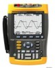
Fluke 190-502/AM Manual
Fluke 190-502/AM Manual
 |
View all Fluke 190-502/AM manuals
Add to My Manuals
Save this manual to your list of manuals |
Fluke 190-502/AM manual content summary:
- Fluke 190-502/AM | Manual - Page 1
ScopeMeter 190 Series II Fluke 190-062, -102, -104, -202, -204, -502 Users Manual May 2011 © 2011 Fluke Corporation. All rights reserved. Specifications are subject to change without notice. All product names are trademarks of their respective companies. MyFlukeStore Shop for Fluke products - Fluke 190-502/AM | Manual - Page 2
SCOPE 1 2 METER 1 RECORDER 1 SCOPE METER 2 CURSOR ZOOM REPLAY CURSOR ZOOM 3 3 REPLAY 3 MyFlukeStore Shop for Fluke products online at: www. .com 1.877.766.5412 - Fluke 190-502/AM | Manual - Page 3
Fluke. Warranty support is available if product is purchased through a Fluke authorized sales outlet or Buyer has paid the applicable international price. Fluke insurance prepaid (FOB Destination), to the nearest Fluke authorized service center. Fluke assumes no risk for damage in transit. Following - Fluke 190-502/AM | Manual - Page 4
To locate an authorized service center, visit us on the World Wide Web: http://www.fluke.com or call Fluke using any of the phone numbers listed below: +1-888-993-5853 in U.S.A. and Canada +31-40-2675200 in Europe +1-425-446-5500 from other countries MyFlukeStore Shop for Fluke products online at - Fluke 190-502/AM | Manual - Page 5
14 Key Illumination...14 Input Connections ...15 Making Input Connections 15 Adjusting the Probe Type Settings 16 Selecting an Input Channel 17 i MyFlukeStore Shop for Fluke products online at: www. .com 1.877.766.5412 - Fluke 190-502/AM | Manual - Page 6
ScopeMeter 190 Series II Users Manual Displaying an Unknown Signal with Connect-and-View 18 Making Automatic Scope Measurements 19 Freezing the Pre-trigger 59 Automatic Trigger Options 60 Triggering on Edges ...61 ii MyFlukeStore Shop for Fluke products online at: www. .com 1.877.766.5412 - Fluke 190-502/AM | Manual - Page 7
Contents (continued) Triggering on External Waveforms (models 190-xx2 64 Triggering on Video Signals 65 Triggering on Pulses ...67 5 Using Memory and PC ...95 Charging the Batteries 96 Replacing the Battery Pack 97 iii MyFlukeStore Shop for Fluke products online at: www. .com 1.877.766.5412 - Fluke 190-502/AM | Manual - Page 8
ScopeMeter 190 Series II Users Manual Calibrating the Voltage Probes 99 Displaying Version and Calibration Information 101 Displaying Battery Information 101 Parts and Accessories 102 Troubleshooting ...107 8 Specifications ...109 Introduction ...109 Oscilloscope ...110 Automatic Scope - Fluke 190-502/AM | Manual - Page 9
instructions in this manual apply to all ScopeMeter 190 Series II versions (hereafter referred to as the instrument or as the test tool). The versions are listed below. The version 190 on the versions 190-x04. Introduction Version 190-062 190-102 190-104 190-202 190-204 190-502 Description Two 60 - Fluke 190-502/AM | Manual - Page 10
Fluke 190 Series II Users Manual Unpacking the Test Tool Kit The following items are 12 (4x) c (2x) c 6 CAT II 1000V CAT III 1000V CAT IV 600V 13 14 12345 - 12345 - 12345 15 Figure 1. ScopeMeter Test Tool Kit 2 MyFlukeStore Shop for Fluke products online at: www. .com 1.877.766.5412 - Fluke 190-502/AM | Manual - Page 11
sheet + CD ROM with Users Manual (multi-language) and FlukeView ScopeMeter Software for Windows demo package (with restricted functionality) 6 Shipment box (basic version only) Unpacking the Test Tool Kit The Fluke 190-062, 190-102, 190-104, 190-202 and 190-204 include also: # Description 7 Voltage - Fluke 190-502/AM | Manual - Page 12
Fluke 190 Series II Users Manual The Fluke 190-502 includes also: # Description 11 Voltage Probe Set (red) 12 Voltage (one red, one black). Fluke 190-xxx /S versions include also the following items (SCC290 kit): # Description 14 FlukeView ScopeMeter Software for Windows activation key (converts - Fluke 190-502/AM | Manual - Page 13
: Read First See explanation in manual Safety Approval Double Insulation (Protection Class II) Earth ground Battery Safety Approval Recycling information Li-Ion Direct Current Do not dispose of this product as unsorted municipal waste. Go to Fluke's website for recycling information. Conforms - Fluke 190-502/AM | Manual - Page 14
Fluke 190 Series II Users Manual Warning To avoid electrical shock or fire: • Use only the Fluke power supply, Model BC190 (Power and adapters supplied with the product, or indicated by Fluke as suitable for the Fluke 190 Series II ScopeMeter series. • Before use, inspect voltage probes, test leads - Fluke 190-502/AM | Manual - Page 15
directly transmitted to the product. • Do not use exposed metal BNC or banana plug connectors. Fluke offers cables with plastic, safety designed BNC connectors suitable for the ScopeMeter product, see Chapter 7 'Optional accessories'. • Do not insert metal objects into connectors. • Use the product - Fluke 190-502/AM | Manual - Page 16
floating' are used in this manual to indicate a measurement in which the product input BNC is connected to a voltage different from earth ground. The isolated input connectors have no exposed metal and are fully insulated to protect against electrical shock. Fluke 190-502: The BNC jacks can - Fluke 190-502/AM | Manual - Page 17
the battery pack. • The battery pack needs to be charged before use. Use only Fluke approved power adapters to charge the battery pack. Refer to Fluke's safety instructions and Users Manual for proper charging instructions. • Do not leave a battery on prolonged charge when not in use. • The battery - Fluke 190-502/AM | Manual - Page 18
Fluke 190 Series II Users Manual • Do not short-circuit a battery pack. Do not keep battery packs in a Dispose of properly: do not dispose of the battery as unsorted municipal waste. Go to Fluke's website for recycling information. • Dispose in discharged condition and cover the battery terminals - Fluke 190-502/AM | Manual - Page 19
basic operations. Powering the Test Tool Follow the procedure (steps 1 through 3) in Figure 2 to power the test tool from a standard ac outlet. See Chapter 6 for instructions on using battery power. Turn the test tool on with the on/off key. The test tool powers up in its last setup configuration - Fluke 190-502/AM | Manual - Page 20
Fluke 190 Series II Users Manual Resetting the Test Tool If you want to reset the test tool to the factory settings, do the following: ; you will see a screen that looks like Figure 3. Figure 3. The Screen After Reset 12 MyFlukeStore Shop for Fluke products online at: www. .com 1.877.766.5412 - Fluke 190-502/AM | Manual - Page 21
keys lets you to step through a menu without changing the settings. To exit the menu at any moment press F4 (CLOSE) 13 MyFlukeStore Shop for Fluke products online at: www. .com 1.877.766.5412 - Fluke 190-502/AM | Manual - Page 22
Fluke 190 Series II Users Manual Hiding Key Labels and Menus You can close a menu or key, and the F1...F4 key labels, apply to the illuminated channel key(s). Off: - MANUAL AUTO TRIGGER On: Manual operating mode. Off: Automatic operating mode, optimizes the trace position, range, time base and - Fluke 190-502/AM | Manual - Page 23
(models 190-xx4), or two safety BNC jack inputs and two safety 4-mm banana jack inputs (models 190-xx2). maximally benefit from having independently isolated floating inputs and to avoid problems caused by improper use, read Chapter 6: "Tips". − Fluke products online at: www. .com 1.877.766.5412 - Fluke 190-502/AM | Manual - Page 24
Fluke 190 Series II Users Manual Adjusting the Probe Type Settings To obtain correct measurement results the test tool probe type factor Current and Temp: select the current probe or temperature probe sensitivity 16 MyFlukeStore Shop for Fluke products online at: www. .com 1.877.766.5412 - Fluke 190-502/AM | Manual - Page 25
pressed keys are illuminated now. The MOVE UP/DOWN key and the RANGE mV/V key applies to all involved input channels. 17 MyFlukeStore Shop for Fluke products online at: www. .com 1.877.766.5412 - Fluke 190-502/AM | Manual - Page 26
Fluke 190 Series II Users Manual Displaying an Unknown Signal with Connect-and-View™ The Connect-and-View feature lets the test tool and MOVE keys at the bottom of the keypad to change the view of the waveform manually. 18 MyFlukeStore Shop for Fluke products online at: www. .com 1.877.766.5412 - Fluke 190-502/AM | Manual - Page 27
. 3 F1 Select the reading number to be displayed, for example READING 2 4 Select on B. The highlight jumps ENTER to the measurements field. 19 MyFlukeStore Shop for Fluke products online at: www. .com 1.877.766.5412 - Fluke 190-502/AM | Manual - Page 28
Fluke 190 Series II Users Manual 5 Open the PEAK menu. ENTER 6 Select the Peak-Peak ENTER measurement. Figure 8 shows an example of The RUN key illumination is off. Figure 8. Hz and V peak-peak as Scope Readings 20 MyFlukeStore Shop for Fluke products online at: www. .com 1.877.766.5412 - Fluke 190-502/AM | Manual - Page 29
smart averaging you can quickly probe around, and incidental waveform changes like a line flyback in video show up on screen instantly. 21 MyFlukeStore Shop for Fluke products online at: www. .com 1.877.766.5412 - Fluke 190-502/AM | Manual - Page 30
Fluke 190 Series II Users Manual Using Persistence, Envelope and Dot-Join to Display Waveforms You can use Persistence to observe dynamic signals to see the upper and lower boundaries of dynamic waveforms (envelope mode). 22 MyFlukeStore Shop for Fluke products online at: www. .com 1.877.766.5412 - Fluke 190-502/AM | Manual - Page 31
. When you select the 2 mV/div range Glitch Detect will automatically be turned Off. In the 2 mV/div range you can set Glitch Detect On manually. 23 MyFlukeStore Shop for Fluke products online at: www. .com 1.877.766.5412 - Fluke 190-502/AM | Manual - Page 32
Fluke 190 Series II Users Manual Suppressing High Frequency Noise Switching the glitch detection off (Glitch: Off) will suppress the high update rate. Normal - optimal trace update rate and zoom range combination 24 MyFlukeStore Shop for Fluke products online at: www. .com 1.877.766.5412 - Fluke 190-502/AM | Manual - Page 33
is identified by an inversed trace identifier ( ) at the right of the waveform, and in the status line below the waveform. 25 MyFlukeStore Shop for Fluke products online at: www. .com 1.877.766.5412 - Fluke 190-502/AM | Manual - Page 34
Fluke 190 Series II Users Manual Variable Input Sensitivity The variable input sensitivity allows the variable input sensitivity on for example input A, do the following: 1 Apply the input signal 2 MANUAL Perform an Auto Set (AUTO must AUTO appear at the top of the screen) An Auto Set will - Fluke 190-502/AM | Manual - Page 35
, use the average function or turn off Display Glitches. 3 Jump to Waveform: and Select ENTER Mathematics... to open the Mathematics menu. 27 MyFlukeStore Shop for Fluke products online at: www. .com 1.877.766.5412 - Fluke 190-502/AM | Manual - Page 36
Fluke 190 Series II Users Manual 4 Select Function: +, -, x or XY- ENTER mode. 5 Select the first waveform: ENTER Source 1: A, B, C or D 6 Select the second SCOPE key labels. 2 F4 Open the Waveform Options menu. 28 MyFlukeStore Shop for Fluke products online at: www. .com 1.877.766.5412 - Fluke 190-502/AM | Manual - Page 37
to linear or logarithmic. Set the vertical amplitude scale to linear or logarithmic. Turn the spectrum function off/on (toggle function). 29 MyFlukeStore Shop for Fluke products online at: www. .com 1.877.766.5412 - Fluke 190-502/AM | Manual - Page 38
Fluke 190 Series II Users Manual Figure 11. Spectrum measurement Comparing Waveforms You can display a fixed reference waveform with the Waveform field and ENTER select Reference... to open the WAVEFORM REFERENCE menu. 30 MyFlukeStore Shop for Fluke products online at: www. .com 1.877.766.5412 - Fluke 190-502/AM | Manual - Page 39
is 0.04 x range/div envelope to be added to the 1 horizontal pixel on the display is 0.0333 x range/div. momentary waveform. 31 MyFlukeStore Shop for Fluke products online at: www. .com 1.877.766.5412 - Fluke 190-502/AM | Manual - Page 40
Fluke 190 Series II Users Manual Pass - Fail Testing You can use a reference waveform as a test template for the actual waveform. If . These functions are described in Chapter 3: "Using Cursors, Zoom and Replay". 32 MyFlukeStore Shop for Fluke products online at: www. .com 1.877.766.5412 - Fluke 190-502/AM | Manual - Page 41
the Scope and Meter Making Automatic Meter Measurements (for models 190-xx4) Making Automatic Meter Measurements (for models 190-xx4) The test tool offers a wide range of automatic .. menu. Figure 12. Meter Screen 33 MyFlukeStore Shop for Fluke products online at: www. .com 1.877.766.5412 - Fluke 190-502/AM | Manual - Page 42
Fluke 190 Series II Users Manual Making Relative Meter Measurements A relative measurement displays the present measurement result relative to a defined activity (voltage, temperature) in relation to a known good value. 34 MyFlukeStore Shop for Fluke products online at: www. .com 1.877.766.5412 - Fluke 190-502/AM | Manual - Page 43
Using the Scope and Meter Making Multimeter Measurements (for models 190-xx2) Making Multimeter Measurements (for models 190-xx2) The screen displays the numeric readings of the measurements Figure 14. Meter Connections 35 MyFlukeStore Shop for Fluke products online at: www. .com 1.877.766.5412 - Fluke 190-502/AM | Manual - Page 44
Fluke 190 Series II Users Manual Measuring Resistance Values To measure a resistance, do the following: 1 Connect the red and black Highlight Ohms. 5 ENTER Select Ohms measurement. Figure 15. Resistor Value Readings 36 MyFlukeStore Shop for Fluke products online at: www. .com 1.877.766.5412 - Fluke 190-502/AM | Manual - Page 45
the instructions about the current probe you are using. To set up the test tool, do the following: 1 Connect a current probe (e.g. Fluke i410 labels. 1 Using the Scope and Meter Making Multimeter Measurements (for models 190-xx2) Figure 16. Measurement Setup 3 F1 Open the MEASUREMENT menu. - Fluke 190-502/AM | Manual - Page 46
Fluke 190 Series II Users Manual 6 Observe the sensitivity of the current probe. Highlight the corresponding sensitivity in the menu, e.g. 1 mV/A. 7 ENTER Accept the current measurement. Now, you will see a screen - Fluke 190-502/AM | Manual - Page 47
the METER key labels. 1 Using the Scope and Meter Making Multimeter Measurements (for models 190-xx2) Now the large reading is the actual input value minus the stored reference value. in relation to a known good value. 39 MyFlukeStore Shop for Fluke products online at: www. .com 1.877.766.5412 - Fluke 190-502/AM | Manual - Page 48
Fluke 190 Series II Users Manual Adjusting the reference value To adjust the reference value, do the following: 5 F3 Display the Adjust step 6 and step 7 until finished. 8 ENTER Enter the new reference value. 40 MyFlukeStore Shop for Fluke products online at: www. .com 1.877.766.5412 - Fluke 190-502/AM | Manual - Page 49
menu, do the following: 1 RECORDER Open the recorder main menu. (See Figure 19). Figure 19. Recorder Main Menu Trendplot Meter is only present in models 190-xx2. 41 MyFlukeStore Shop for Fluke products online at: www. .com 1.877.766.5412 - Fluke 190-502/AM | Manual - Page 50
Fluke 190 Series II Users Manual Plotting Measurements Over Time (TrendPlot™) Use the TrendPlot function to plot a graph of Scope or Meter measurements ( . The present reading appears on top of the screen. (See Figure 20.) 42 MyFlukeStore Shop for Fluke products online at: www. .com 1.877.766.5412 - Fluke 190-502/AM | Manual - Page 51
is not possible on cursor related measurements. As an alternative you may use FlukeView logging of readings. Figure 20. TrendPlot Reading 43 MyFlukeStore Shop for Fluke products online at: www. .com 1.877.766.5412 - Fluke 190-502/AM | Manual - Page 52
Fluke 190 Series II Users Manual Displaying Recorded Data When in normal view (NORMAL), only the twelve most recently recorded divisions ENTER Start Turning Off the TrendPlot Display 9 F4 Exit the recorder function. 44 MyFlukeStore Shop for Fluke products online at: www. .com 1.877.766.5412 - Fluke 190-502/AM | Manual - Page 53
that fits the memory. Note For accurate recordings it is advised to let the instrument first warm up for five minutes. 45 MyFlukeStore Shop for Fluke products online at: www. .com 1.877.766.5412 - Fluke 190-502/AM | Manual - Page 54
Fluke 190 Series II Users Manual Displaying Recorded Data In Normal view, the samples that roll off the screen are stored in field, select ENTER Single Sweep and accept the recorder options. 7 F1 Start recording. 46 MyFlukeStore Shop for Fluke products online at: www. .com 1.877.766.5412 - Fluke 190-502/AM | Manual - Page 55
xx4) or on Ext. (models 190-xx2) to open the START SINGLE SWEEP ON TRIGGERING or the START SINGLE SWEEP ON EXT. menu. 8 Select one of the Conditions: ENTER and accept the selection. For external triggering (190-xx2) continue at step 9. 47 MyFlukeStore Shop for Fluke products online at: www - Fluke 190-502/AM | Manual - Page 56
Fluke 190 Series II Users Manual 9 Select the desired trigger slope ENTER (Slope:) and jump to Level: 10 Select the 0.12V or 1.2V analysis. These functions are described in Chapter 3: "Using Replay, Zoom and Cursors". 48 MyFlukeStore Shop for Fluke products online at: www. .com 1.877.766.5412 - Fluke 190-502/AM | Manual - Page 57
find the screen of your interest. This feature lets you capture and view signals even if you did not press HOLD. 49 MyFlukeStore Shop for Fluke products online at: www. .com 1.877.766.5412 - Fluke 190-502/AM | Manual - Page 58
Fluke 190 Series II Users Manual Replaying Step-by-Step To step through the last scope screens, do the following: 1 REPLAY From scope mode, can use the zoom and cursor functions to study the signal in more detail. 50 MyFlukeStore Shop for Fluke products online at: www. .com 1.877.766.5412 - Fluke 190-502/AM | Manual - Page 59
to trigger and capture 100 intermittent glitches or you could capture 100 UPS startups. For triggering, see Chapter 4: "Triggering on Waveforms". 51 MyFlukeStore Shop for Fluke products online at: www. .com 1.877.766.5412 - Fluke 190-502/AM | Manual - Page 60
Fluke 190 Series II Users Manual Zooming in on a Waveform To obtain a more detailed view of a waveform, you can zoom in on a waveform using in memory. Turning Off the Zoom Function 4 F4 Turn off the ZOOM function. 52 MyFlukeStore Shop for Fluke products online at: www. .com 1.877.766.5412 - Fluke 190-502/AM | Manual - Page 61
at the cursors. (See Figure 25.) Use horizontal cursors to measure the amplitude, high or low value, or overshoot of a waveform. 53 MyFlukeStore Shop for Fluke products online at: www. .com 1.877.766.5412 - Fluke 190-502/AM | Manual - Page 62
Fluke 190 Series II Users Manual Using Vertical Cursors on a Waveform To use the cursors for a time measurement (T, 1/T), for a mVs-mAs-mWs measurement two markers. (See Figure 26.) 9 F4 Select OFF to turn off the cursors. MyFlukeStore Shop for Fluke products online at: www. .com 1.877.766.5412 - Fluke 190-502/AM | Manual - Page 63
From Spectrum measurement display the cursor key label. 2 Move the cursor and observe the readings at the top of the screen. 55 MyFlukeStore Shop for Fluke products online at: www. .com 1.877.766.5412 - Fluke 190-502/AM | Manual - Page 64
Fluke 190 Series II Users Manual Making Rise Time Measurements To measure rise time, do the multiple traces select the required trace A, B, C, D or M (if a math function is active). Select MANUAL or AUTO (this automatically does steps 5 to 7). Move the upper cursor to 100% of the trace height. - Fluke 190-502/AM | Manual - Page 65
of the signal. (See next section.) • For dedicated applications, use one of the three manual trigger functions: • Edge triggering • Video triggering • Pulse Width triggering • External Triggering (models 190-xx2 only) 57 MyFlukeStore Shop for Fluke products online at: www. .com 1.877.766.5412 - Fluke 190-502/AM | Manual - Page 66
Fluke 190 series II Users Manual Setting Trigger Level and Slope The Connect-and-View™ function enables hands-off triggering to display complex unknown signals. When your test tool is in manual range, do the following: MANUAL AUTO Perform an auto set. AUTO appears at the top right of the screen - Fluke 190-502/AM | Manual - Page 67
used as the trigger source with a positive slope. The 500.0 ms indicates the (positive) delay between trigger point and waveform display. 59 MyFlukeStore Shop for Fluke products online at: www. .com 1.877.766.5412 - Fluke 190-502/AM | Manual - Page 68
Fluke 190 series II Users Manual Automatic Trigger Options In the trigger menu, settings for automatic triggering . However, when you measure frequencies lower than 15 Hz, the test tool must be instructed to analyze low frequency components for automatic triggering: 4 Select > 1 HZ and return to - Fluke 190-502/AM | Manual - Page 69
If the signal is unstable or has a very low frequency, use edge triggering to obtain full manual trigger control. To trigger on rising edges of the input A waveform, do the following: 1 of specific edge trigger settings: 61 MyFlukeStore Shop for Fluke products online at: www. .com 1.877.766.5412 - Fluke 190-502/AM | Manual - Page 70
Fluke 190 series II Users Manual Triggering on Noisy Waveforms To reduce jitter on the the input A waveform, continue from step 3 (page 61) again: 4 Select Single Shot. ENTER The word MANUAL appears at the top of the screen indicating that the test tool is waiting for a trigger. As soon as - Fluke 190-502/AM | Manual - Page 71
N 8 Adjust the trigger level Traces with N-Cycle triggering (N=2) and without N-Cycle triggering are shown in Figure 31. Figure 31. N-Cycle triggering 63 MyFlukeStore Shop for Fluke products online at: www. .com 1.877.766.5412 - Fluke 190-502/AM | Manual - Page 72
Fluke 190 series II Users Manual Triggering on External Waveforms (models 190-xx2) Use external triggering when you want to display waveforms on inputs A and B logic signals. 3 F1 Select Ext (external) edge trigger. 64 MyFlukeStore Shop for Fluke products online at: www. .com 1.877.766.5412 - Fluke 190-502/AM | Manual - Page 73
the key labels at the bottom of the screen have been changed to allow further selection of specific video trigger settings. 65 MyFlukeStore Shop for Fluke products online at: www. .com 1.877.766.5412 - Fluke 190-502/AM | Manual - Page 74
Fluke 190 series II Users Manual Triggering on Video Frames Use FIELD 1 or FIELD 2 to trigger either on the first half of the frame ( selected line number. The screen is continuously updated with the signal of line 123. 66 MyFlukeStore Shop for Fluke products online at: www. .com 1.877.766.5412 - Fluke 190-502/AM | Manual - Page 75
the pulse width. 9 Select 5 ms. All narrow positive pulses shorter than 5 ms are now displayed on the screen. (See Figure 33). 67 MyFlukeStore Shop for Fluke products online at: www. .com 1.877.766.5412 - Fluke 190-502/AM | Manual - Page 76
Fluke 190 series II Users Manual Tip The test tool stores all triggered screens in the replay memory. For example, if you setup your Glitches 3 Select Pulse Width on A... to ENTER open the TRIGGER ON PULSE WIDTH menu. 68 MyFlukeStore Shop for Fluke products online at: www. .com 1.877.766.5412 - Fluke 190-502/AM | Manual - Page 77
keys to adjust the pulse width. 8 Select 110 ms. 4 Triggering on Waveforms Triggering on Pulses Figure 34. Triggering on Missing Pulses 69 MyFlukeStore Shop for Fluke products online at: www. .com 1.877.766.5412 - Fluke 190-502/AM | Manual - Page 78
Fluke 190 series II Users Manual 70 MyFlukeStore Shop for Fluke products online at: www. .com 1.877.766.5412 - Fluke 190-502/AM | Manual - Page 79
channels and are covered with dust covers when not in use. USB stick Mini USB Figure 35. Test Tool USB Connections 71 MyFlukeStore Shop for Fluke products online at: www. .com 1.877.766.5412 - Fluke 190-502/AM | Manual - Page 80
Fluke 190 series II Users Manual Saving and Recalling You can: • Save screens and setups to internal memory, and recall them screen setup + replay screens/record data setup + trendplot data screen image (imagexxx.bmp) 72 MyFlukeStore Shop for Fluke products online at: www. .com 1.877.766.5412 - Fluke 190-502/AM | Manual - Page 81
to modify the default name see below 'Editing Names'. 5 ENTER Save the Screen+setup. To resume your measurements press HOLD RUN . 73 MyFlukeStore Shop for Fluke products online at: www. .com 1.877.766.5412 - Fluke 190-502/AM | Manual - Page 82
Fluke 190 series II Users Manual All memories in use If no free memory locations are available a message pops up that proposes to you from step 8 as follows: 9 Highlight SET DEFAULT to save ENTER the new default name 74 MyFlukeStore Shop for Fluke products online at: www. .com 1.877.766.5412 - Fluke 190-502/AM | Manual - Page 83
, then delete one or more memory locations, and save again. If you want to overwrite the oldest data set, - press F4 . 75 MyFlukeStore Shop for Fluke products online at: www. .com 1.877.766.5412 - Fluke 190-502/AM | Manual - Page 84
Fluke 190 series II Users Manual Deleting Screens with Associated Setups To delete a screen and associated setup, do the following: 1 to compare it to an actually measured waveform, see Chapter 1 'Comparing Waveforms'. 76 MyFlukeStore Shop for Fluke products online at: www. .com 1.877.766.5412 - Fluke 190-502/AM | Manual - Page 85
the viewer. 7 8 F3 Scroll through all stored screens. Print screen, saves the screen to USB device (if connected) or internal memory. 77 MyFlukeStore Shop for Fluke products online at: www. .com 1.877.766.5412 - Fluke 190-502/AM | Manual - Page 86
Fluke 190 series II Users Manual 9 F4 Exit the View mode. Note: In the VIEW mode the replay screens of a saved 'record+ USB device. 4 Highlight RENAME. 5 ENTER Accept your choice and jump to the filename field. 78 MyFlukeStore Shop for Fluke products online at: www. .com 1.877.766.5412 - Fluke 190-502/AM | Manual - Page 87
Recalling 6 F2 Select the file to be copied or moved, Or Select all files 7 ENTER Copy or delete the selected files. 79 MyFlukeStore Shop for Fluke products online at: www. .com 1.877.766.5412 - Fluke 190-502/AM | Manual - Page 88
Fluke 190 series II Users Manual Using FlukeView® With the FlukeView® software you can upload waveform ® version can be ordered using ordering code SW90W. For use with the Fluke Series II ScopeMeter test tools FlukeView® ScopeMeter release V5.0 or higher is required. − The test tool input channels - Fluke 190-502/AM | Manual - Page 89
Accessories The following illustrations show the use of the standard accessories such as voltage probes, test leads, and the various clips. 81 MyFlukeStore Shop for Fluke products online at: www. .com 1.877.766.5412 - Fluke 190-502/AM | Manual - Page 90
Fluke 190 Series II Users Manual A Figure 37. HF Voltage Probe Connection Using Ground Spring Warning To avoid electrical shock or fire, do not connect the ground spring to voltages higher than 30 Vrms from earth ground. Figure 38. HF Voltage Probe Connection Using Probe Tip to BNC Adapter (190- - Fluke 190-502/AM | Manual - Page 91
having four independent instruments. The advantages of having independently floating isolated inputs are: • It allows simultaneous measurement of independently floating signals. 83 MyFlukeStore Shop for Fluke products online at: www. .com 1.877.766.5412 - Fluke 190-502/AM | Manual - Page 92
Fluke 190 Series II Users Manual • Additional safety. Since the commons are not directly connected, the chance of causing short circuit when measuring multiple present on the ground ring near the probe tip, see Figure 41. 84 MyFlukeStore Shop for Fluke products online at: www. .com 1.877.766.5412 - Fluke 190-502/AM | Manual - Page 93
BUS ANALOG GROUND DIGITAL GROUND D A Figure 43. Correct connection of reference leads Figure 42. Parasitic capacitance between analog and digital reference 85 MyFlukeStore Shop for Fluke products online at: www. .com 1.877.766.5412 - Fluke 190-502/AM | Manual - Page 94
Fluke 190 Series II Users Manual ANALOG INPUT DIGITAL CONTROLLER ANALOG GROUND DIGITAL GROUND D angle while placed on a table. The typical position is shown in Figure 45. Kensington® lock support Power adapter input Figure 45. Using the Tilt Stand Note An optional Hanging Hook, ordering code HH290 - Fluke 190-502/AM | Manual - Page 95
test tool. The figure below shows how to attach the strap correctly to the test tool. Figure 46. Fixing the Hangstrap 87 MyFlukeStore Shop for Fluke products online at: www. .com 1.877.766.5412 - Fluke 190-502/AM | Manual - Page 96
Fluke 190 Series II Users Manual Resetting the Test Tool If you want to reset the test tool to the factory settings, without clearing the keys, e.g. the SCOPE key. You can also close a menu using the F4 CLOSE. softkey 88 MyFlukeStore Shop for Fluke products online at: www. .com 1.877.766.5412 - Fluke 190-502/AM | Manual - Page 97
USER Display the USER key labels. 2 F4 3 4 Enable the arrow keys for manual contrast and backlight adjustment. Adjust the contrast of the screen. Change the backlight. Note 'Specifications', section 'Miscellaneous'. 89 MyFlukeStore Shop for Fluke products online at: www. .com 1.877.766.5412 - Fluke 190-502/AM | Manual - Page 98
Fluke 190 Series II Users Manual Changing Date and Time The test tool has a date and time clock. For example, to change the date to 19 there is no automatic power shutdown, and the display AUTO-off function is inactive. 90 MyFlukeStore Shop for Fluke products online at: www. .com 1.877.766.5412 - Fluke 190-502/AM | Manual - Page 99
. 4 Select Display Auto-OFF ENTER 30 Seconds or 5 Minutes . The display will be turned off after the selected time is elapsed. 91 MyFlukeStore Shop for Fluke products online at: www. .com 1.877.766.5412 - Fluke 190-502/AM | Manual - Page 100
Fluke 190 Series II Users Manual To turn on the display again do one of the following -andView function responds more quickly. The response is quicker because the test tool is instructed not to analyze low frequency signal components. However, when you measure frequencies lower than 15 Hz, - Fluke 190-502/AM | Manual - Page 101
can either be set to dc or left unchanged: 5 Select Unchanged. ENTER When you press the AUTO-MANUAL (auto set) key glitch capture can either be set to On or left unchanged: 6 Select Unchanged the Auto Set Options 93 MyFlukeStore Shop for Fluke products online at: www. .com 1.877.766.5412 - Fluke 190-502/AM | Manual - Page 102
Fluke 190 Series II Users Manual 94 MyFlukeStore Shop for Fluke products online at: www. .com 1.877.766.5412 - Fluke 190-502/AM | Manual - Page 103
Chapter This chapter covers basic maintenance procedures that can be performed by the user. For complete service, disassembly, repair, and calibration information, see the Service Manual. (www.fluke.com) Warning • Have an approved technician repair the product. • Use only specified replacement parts - Fluke 190-502/AM | Manual - Page 104
Fluke 190 Series II Users Manual Charging the Batteries At delivery, the Li-ion batteries may be empty charging. Figure 47. Charging the Batteries Alternatively, you may choose to exchange the battery (Fluke accessory BP290 or BP291) with a fully charged one, and use the external battery charger - Fluke 190-502/AM | Manual - Page 105
Replacing the Battery Pack Warning Use only the Fluke BP290 (not recommended for 190-xx4) or BP291 for replacement! When no adapter power is supplied, Tool Replacing the Battery Pack Figure 48. Unlocking the Battery Cover 97 MyFlukeStore Shop for Fluke products online at: www. .com 1.877.766.5412 - Fluke 190-502/AM | Manual - Page 106
Fluke 190 Series II Users Manual Figure 49. Removing the Battery Cover Figure 50. Removing the Battery 98 MyFlukeStore Shop for Fluke products online at: www. .com 1.877.766.5412 - Fluke 190-502/AM | Manual - Page 107
) you can continue at step 5. 3 Select Probe Type: Voltage, and ENTER Attenuation: 10:1. Probe Cal Ref. Figure 51. Adjusting Voltage Probes 99 MyFlukeStore Shop for Fluke products online at: www. .com 1.877.766.5412 - Fluke 190-502/AM | Manual - Page 108
Fluke 190 Series II Users Manual A message appears asking you whether to start the 10:1 probe housing until a pure square wave is displayed. For instructions to access the trimmer screw in the probe housing see the probe instruction sheet. The test tool automatically calibrates itself to the - Fluke 190-502/AM | Manual - Page 109
(see Chapter 8) are based on a 1 year calibration cycle. Recalibration must be carried out by qualified personnel. Contact your local Fluke representative for recalibration. 4 F4 Return to the previous screen. 'Level' indicates the available battery capacity as a percentage of the present - Fluke 190-502/AM | Manual - Page 110
Fluke 190 Series II Users Manual Parts and Accessories The following tables list the user-replaceable parts and specific optional accessories for the various test tool models. For more optional accessories, see www.fluke.com. To order replacement parts or additional accessories, contact your - Fluke 190-502/AM | Manual - Page 111
(Red or Blue or Gray or Green), designed for use with the Fluke 190-062,-102,-104,-202, and -204 test tool. The set includes the (black) See Figure 1 on page 2 for item reference. See the VPS410 instruction sheet for voltage/CAT ratings. Replacement Set for Voltage Probe VPS410 The set includes the - Fluke 190-502/AM | Manual - Page 112
Fluke 190 Series II Users Manual Replacement Parts (continued) Voltage Probe Set, designed for use with the Fluke 190-502 test tool. The set Adapter See Figure 1 on page 2 for item reference. See the VPS510 instruction sheet for voltage/CAT ratings. Replacement Set for Voltage Probe VPS510 The set - Fluke 190-502/AM | Manual - Page 113
two pieces, black) Li-ion battery (26 Wh, not recommended for models 190-xx4) Li-ion battery (52 Wh) Hangstrap 7 Maintaining the Test Tool into an operational version. • Hard Shell Carrying Case C290 FlukeView® ScopeMeter® Software for Windows® (full version) Hard Shell Carrying Case Ordering - Fluke 190-502/AM | Manual - Page 114
Fluke 190 Series II Users Manual Optional accessories (continued) External Battery Charger, charges BP291 externally using BC190 High Working Voltage BNC (fully isolated). EBC290 VPS420-R HH290 PM9091 PM9092 PM9093 106 MyFlukeStore Shop for Fluke products online at: www. .com 1.877.766.5412 - Fluke 190-502/AM | Manual - Page 115
You might have a problem with the screen contrast. Press USER , then press F4 . Now you can use the arrow keys to adjust the contrast. 7 Maintaining the Test Tool Troubleshooting • The display 'auto , see Appendix A. MyFlukeStore Shop for Fluke products online at: www. .com 1.877.766.5412 107 - Fluke 190-502/AM | Manual - Page 116
Fluke 190 Series II Users Manual Battery Operated Fluke Accessories Do Not Function • When using battery operated Fluke accessories, always first check the battery condition of the accessory with a Fluke multimeter. 108 MyFlukeStore Shop for Fluke products online at: www. .com 1.877.766.5412 - Fluke 190-502/AM | Manual - Page 117
mean of a range of identical ScopeMeter test tools. The Test Tool meets the specified accuracy 30 minutes and two complete acquisitions after power on. Specifications are based on a 1-year calibration cycle. Environmental Data The environmental data mentioned in this manual are based on the results - Fluke 190-502/AM | Manual - Page 118
Fluke 190 Series II Users Manual Oscilloscope Isolated Inputs A,B, C and D (Vertical) Number of Channels Fluke 190-xx2 2 (A, B) Fluke 190-xx4 4 (A,B,C,D) Bandwidth, DC Coupled FLUKE 190-502 500 MHz (-3 dB) FLUKE 190-2xx 200 MHz (-3 dB) FLUKE 190-1xx 100 MHz (-3 dB) FLUKE 190-062 60 MHz (-3 dB - Fluke 190-502/AM | Manual - Page 119
μs to 120 s/div 125 MS/s Record Length: see table below. FLUKE 190-062: 10 ns to 4 μs /div (all channels)...........up to 625 190-062: 625 MS/s 190-102/104: 1.25 GS/s 190-202/204: 2.5 GS/s (1 or 2 channels on) 190-204: 1.25 GS/s (3 or 4 channels on) 190-502: 5 GS/s (1 channel on) 190-502 - Fluke 190-502/AM | Manual - Page 120
division 500 MHz (FLUKE 190-502 1 division 600 MHz (FLUKE 190-502 2 divisions 200 MHz (FLUKE 190-2xx 1 division 250 MHz (FLUKE 190-2xx 2 divisions 100 MHz (FLUKE 190-1xx 1 division 150 MHz (FLUKE 190-1xx 2 divisions 60 MHz (FLUKE 190-062 1 division 100 MHz (FLUKE 190-062 2 divisions Isolated - Fluke 190-502/AM | Manual - Page 121
mV 1 MHz to max. bandwidth 20 mV Automatic Capturing Scope Screens Capacity 100 Scope Screens For viewing screens, see Replay function. 113 MyFlukeStore Shop for Fluke products online at: www. .com 1.877.766.5412 - Fluke 190-502/AM | Manual - Page 122
Fluke 190 Series II Users Manual Automatic Scope Measurements The accuracy of all readings is within ± (% of reading + number of counts) from 18 roll off starts affecting accuracy. Normal Mode DC Rejection 50 dB 114 MyFlukeStore Shop for Fluke products online at: www. .com 1.877.766.5412 - Fluke 190-502/AM | Manual - Page 123
Scale Reading 999 counts Accuracy 1 Hz to full bandwidth 0.5 % +2 counts) (5 s/div to 10 ns/div and 10 periods on the screen). 115 MyFlukeStore Shop for Fluke products online at: www. .com 1.877.766.5412 - Fluke 190-502/AM | Manual - Page 124
Fluke 190 Series II Users Manual Duty Cycle (DUTY) Range 4.0 % to 98.0 % Resolution 0.1 % (when period > 2 div) Full Scale Reading 999 counts (3-digit display) Reactive (VAR VA)2-W2) Full Scale Reading 999 counts 116 MyFlukeStore Shop for Fluke products online at: www. .com 1.877.766.5412 - Fluke 190-502/AM | Manual - Page 125
one mW in 50 Ω or 600 Ω dB on VDC, VAC, or VAC+DC Accuracy same as VDC, VAC, VAC+DC 8 Specifications Meter Measurements for Fluke 190-xx4 Meter Measurements for Fluke 190-xx4 Four of the Automatic Scope Measurements as defined above may be displayed at the same time, using larger screen area for - Fluke 190-502/AM | Manual - Page 126
V CAT III 600 V CAT IV (For detailed specifications, see "Safety") Max. Input Voltage Fluke 190-502 1000 V CAT II 600 V CAT III (For detailed specifications, see "Safety") Meter Functions Ranging Auto, Manual Modes Normal, Relative General DC Common Mode Rejection (CMRR 100 dB AC Common Mode - Fluke 190-502/AM | Manual - Page 127
frequencies the frequency roll off of the Meter input starts affecting accuracy. Normal Mode DC Rejection 50 dB 8 Specifications Meter Measurements for Fluke 190-xx2 AC+DC Voltage (True RMS) Ranges......500.0 mV, 5.000 V, 50.00 V, 500.0 V, 1100 V Full Scale Reading 5000 counts Accuracy DC to - Fluke 190-502/AM | Manual - Page 128
Fluke 190 Series II Users Manual Recorder TrendPlot (Meter or Scope) Chart recorder that plots a graph of min and max values of Meter or Continuous Roll Start/Stop on Trigger Time Reference time from start, time of day 120 MyFlukeStore Shop for Fluke products online at: www. .com 1.877.766.5412 - Fluke 190-502/AM | Manual - Page 129
time A x s (current over time between cursors) V x s (voltage over time between cursors) W x s (power over time between cursors using powertrace AxB or CxD) 121 MyFlukeStore Shop for Fluke products online at: www. .com 1.877.766.5412 - Fluke 190-502/AM | Manual - Page 130
Fluke 190 Series II Users Manual Miscellaneous Display View Area 126.8 x 88.4 mm (4.99 x 3.48 inches cd/ m2 Display Auto-OFF time (battery saving) .........30 seconds, 5 minutes or disabled Power FLUKE 190-xx4: Rechargeable Li-ion Battery (model BP291): Operating Time up to 7 hours (Low Intensity) - Fluke 190-502/AM | Manual - Page 131
USB stick, 2GB max Mechanical Size 265 x 190 x 70 mm (10.5 x 7.5 x 2.8 in) Weight FLUKE 190-xx4........... 2.2 kg (4.8 lbs) including battery FLUKE 190-5xx........... 2.2 kg (4.8 lbs) including battery FLUKE 190-xx2........... 2.1 kg (4.6 lbs) including battery 8 Specifications Miscellaneous - Fluke 190-502/AM | Manual - Page 132
Fluke 190 Series II Users Manual Environmental Environmental MIL-PRF-28800F, Class 2 Temperature Operating: CATII 1000V 3 km (10 000 feet) CATIV 600V, CATIII 1000V 2 km (6 600 feet) Operating, Fluke 190-502: CATIII 300V, CATII 600V 3 km (10 000 feet) CATIV 300V, CATIII 600V 2 km (6 600 feet - Fluke 190-502/AM | Manual - Page 133
test tool + VPS410) From any terminal to earth ground ......... 1000 V CAT III 600 V CAT IV Between any terminal 1000 V CAT III 600 V CAT IV FLUKE 190-502 (test tool or test tool + VPS410) From any terminal to earth ground .......... 1000 V CAT II 600 V CAT III Between any terminal 1000 V CAT II - Fluke 190-502/AM | Manual - Page 134
Fluke 190 Series II Users Manual MAX. INPUT VOLTAGE (Vrms) 500 200 100 50 20 10 5 2 1 0.01 0.02 0.05 0.1 0.2 0.5 1 2 5 10 20 50 100 FREQUENCY (MHz) Figure 52. Max. Input Voltage vs. Frequency VOLTAGE (Vrms) 1000 500 CAT III (-502: CAT II) CAT IV (-502: CAT III) 200 100 50 30 20 10 5 2 1 0.01 0. - Fluke 190-502/AM | Manual - Page 135
1 % 20 kHz to 1 MHz 2 % 1 MHz to 25 MHz 3 % For higher frequencies the probe's roll off starts affecting the accuracy. For further probe specifications see the instruction sheet supplied with the VPS510 probe set. 127 MyFlukeStore Shop for Fluke products online at: www. .com 1.877.766.5412 - Fluke 190-502/AM | Manual - Page 136
Fluke 190 Series II Users Manual Electromagnetic Immunity The Fluke 190 Series II test tools, including standard accessories, conform with the EEC directive 2004/108 E = 3V/m 500 mV to 1000 V, 500 Ohm to 30 MOhm ranges 128 MyFlukeStore Shop for Fluke products online at: www. .com 1.877.766.5412 - Fluke 190-502/AM | Manual - Page 137
No visible disturbance Frequency range 2 GHz to 2.7 GHz 8 Specifications Electromagnetic Immunity Table 6 E = 1V/m 500 mV to 1000 V , 500 Ohm to 30 MOhm ranges 129 MyFlukeStore Shop for Fluke products online at: www. .com 1.877.766.5412 - Fluke 190-502/AM | Manual - Page 138
Fluke 190 Series II Users Manual 130 MyFlukeStore Shop for Fluke products online at: www. .com 1.877.766.5412 - Fluke 190-502/AM | Manual - Page 139
the Test Tool, 101 Calibrating Voltage Probes, 99, 122 calibration date, 101 number, 101 Capturing 100 Screens, 51, 113 Case, 105 131 MyFlukeStore Shop for Fluke products online at: www. .com 1.877.766.5412 - Fluke 190-502/AM | Manual - Page 140
ScopeMeter 190 Series II Users Manual Charge Time, 122 Charging, 96 Cleaning, 95 Clear Menu, 14, 88 Comparing Waveforms, 30 Connect-and-View, 18, , 106 Hook Clips, 3, 103, 104 Horizontal Cursors, 53 Humidity, 124 Hz, 115 132 MyFlukeStore Shop for Fluke products online at: www. .com 1.877.766.5412 - Fluke 190-502/AM | Manual - Page 141
Power Factor, 116 Power Factor (Power...), 19 power shutdown, 90 Powering the Test Tool, 11 Pre Trigger, 59 Print Screen, 75 133 MyFlukeStore Shop for Fluke products online at: www. .com 1.877.766.5412 - Fluke 190-502/AM | Manual - Page 142
ScopeMeter 190 Series II Users Manual Probe Accessory Extension Set, 105 Probe Calibration, 99, 122 Probe Replacement Set, 103, 104 Probe Tip to BNC Adapter, 4 Probe Type, 16, 33 Pulse Trigger, 67 Pulse Width, 116 Pulse Width Trigger, 113 -R- Readings, 19 190-104, 33, 35 190-204, 33 Recalibrating, - Fluke 190-502/AM | Manual - Page 143
58 External, 64 N-Cycle, 63 On Edges, 61 On Pulses, 67 On Video, 65 On Waveforms, 57 Troubleshooting, 107 TV Triggering, 65 -U- Unpacking, 2 USB drivers, 80 USB Interface Cable, 3 USB Ports, 71 USB 27 -Z- Zoom, 52, 121 135 MyFlukeStore Shop for Fluke products online at: www. .com 1.877.766.5412 - Fluke 190-502/AM | Manual - Page 144
ScopeMeter 190 Series II Users Manual 136 MyFlukeStore Shop for Fluke products online at: www. .com 1.877.766.5412 - Fluke 190-502/AM | Manual - Page 145
Appendices Appendix Title Page A Installing USB Drivers A-1 B Battery Pack MSDS B-1 C Instrument Security Procedures C-1 MyFlukeStore Shop for Fluke products online at: www. .com 1.877.766.5412 - Fluke 190-502/AM | Manual - Page 146
MyFlukeStore Shop for Fluke products online at: www. .com 1.877.766.5412 - Fluke 190-502/AM | Manual - Page 147
. This is required for installation on Win 7. Note: The Fluke 190 Series II instrument requires two drivers to be loaded in sequence. − 1st it requires installation of the Fluke 190 ScopeMeter USB driver − 2nd it requires installation of the Fluke USB Serial port Both of these drivers need to be - Fluke 190-502/AM | Manual - Page 148
Fluke 190 Series II Users Manual Installing the USB Drivers To install the USB drivers, do the following: 1 Connect the Fluke 190 Series II is not required to power off. When there is no driver loaded for the Fluke 190 Series II instrument, Windows will show that there is New Hardware detected, and - Fluke 190-502/AM | Manual - Page 149
supplied with the ScopeMeter, which contains the drivers. 3 Follow the instructions on screen. When the driver has finished installation click 'Finish' to complete the first step of the driver installation. A Appendices Installing USB Drivers A-3 MyFlukeStore Shop for Fluke - Fluke 190-502/AM | Manual - Page 150
Fluke 190 Series II Users Manual 4 instructions on screen. When the driver finished installation click 'Finish' to complete the final step of the driver installation. You are now ready to use the ScopeMeter with FlukeView Software SW90W from version V5.0 onwards. A-4 MyFlukeStore Shop for Fluke - Fluke 190-502/AM | Manual - Page 151
the device manager for your Windows version) From the device manager click on the + sign to Expand the 'Universal Serial Bus controllers'. The 'Fluke 190 ScopeMeter' should be listed here. From the device manager click on the + sign to Expand the 'Ports (COM & LPT)' Universal Serial Bus controllers - Fluke 190-502/AM | Manual - Page 152
the port number. 2) Sometimes other applications installed on the PC automatically occupy the newly created port. On most situations it is sufficient to unplug the Fluke 190 Series II ScopeMeter USB cable shortly and then reconnect the cable. A-6 MyFlukeStore Shop for - Fluke 190-502/AM | Manual - Page 153
Li-ion Battery Pack Contact Fluke for a Battery Material Safety Data Sheet (MSDS) or Compliance Information. B Appendices Battery Pack MSDS Appendix B Battery Pack MSDS B-1 MyFlukeStore Shop for Fluke products online at: www. .com 1.877.766.5412 - Fluke 190-502/AM | Manual - Page 154
Fluke 190 Series II Users Manual B-2 MyFlukeStore Shop for Fluke products online at: www. .com 1.877.766.5412 - Fluke 190-502/AM | Manual - Page 155
Appendices Instrument Security Procedures Appendix C Instrument Security Procedures Memory The 190 Series II ScopeMeter test tools has the following memory devices: 1. D4000 Controller " use by Product Development). C-1 MyFlukeStore Shop for Fluke products online at: www. .com 1.877.766.5412 - Fluke 190-502/AM | Manual - Page 156
Fluke 190 Series II Users Manual The instrument firmware can be loaded using a dedicated Fluke software program (only available for Fluke (authorized) workshops). Calibration constants stored in D5000, D5002 can be read using special remote interface commands (only available for use by Product - Fluke 190-502/AM | Manual - Page 157
sources, open the battery door present at the rear panel and lift the battery out of the instrument. C Appendices Instrument Security Procedures C-3 MyFlukeStore Shop for Fluke products online at: www. .com 1.877.766.5412 - Fluke 190-502/AM | Manual - Page 158
Fluke 190 Series II Users Manual C-4 MyFlukeStore Shop for Fluke products online at: www. .com 1.877.766.5412
-
 1
1 -
 2
2 -
 3
3 -
 4
4 -
 5
5 -
 6
6 -
 7
7 -
8
-
9
-
10
-
11
-
12
-
13
-
14
-
15
-
16
-
17
-
18
-
19
-
20
-
21
-
22
-
23
-
24
-
25
-
26
-
27
-
28
-
29
-
30
-
31
-
32
-
33
-
34
-
35
-
36
-
37
-
38
-
39
-
40
-
41
-
42
-
43
-
44
-
45
-
46
-
47
-
48
-
49
-
50
-
51
-
52
-
53
-
54
-
55
-
56
-
57
-
58
-
59
-
60
-
61
-
62
-
63
-
64
-
65
-
66
-
67
-
68
-
69
-
70
-
71
-
72
-
73
-
74
-
75
-
76
-
77
-
78
-
79
-
80
-
81
-
82
-
83
-
84
-
85
-
86
-
87
-
88
-
89
-
90
-
91
-
92
-
93
-
94
-
95
-
96
-
97
-
98
-
99
-
100
-
101
-
102
-
103
-
104
-
105
-
106
-
107
-
108
-
109
-
110
-
111
-
112
-
113
-
114
-
115
-
116
-
117
-
118
-
119
-
120
-
121
-
122
-
123
-
124
-
125
-
126
-
127
-
128
-
129
-
130
-
131
-
132
-
133
-
134
-
135
-
136
-
137
-
138
-
139
-
140
-
141
-
142
-
143
-
144
-
145
-
146
-
147
-
148
-
149
-
150
-
151
-
152
-
153
-
154
-
155
-
156
-
157
-
158
 |
 |

May 2011
© 2011 Fluke Corporation. All rights reserved. Specifications are subject to change without notice.
All product names are trademarks of their respective companies.
ScopeMeter 190 Series II
Fluke 190-062, -102, -104, -202, -204, -502
Users Manual
Shop for Fluke products online at:
1.877.766.5412
www.
MyFlukeStore
.com