Fluke 787 FE 787 Users Manual
Fluke 787 Manual
 |
View all Fluke 787 manuals
Add to My Manuals
Save this manual to your list of manuals |
Fluke 787 manual content summary:
- Fluke 787 | FE 787 Users Manual - Page 1
April 1997, Rev.3, 12/01 © 1997, 1898, 2000, 2001 Fluke Corporation, All rights reserved. Printed in U.S.A. All product names are trademarks of their respective companies. ® 787 ProcessMeter Users Manual - Fluke 787 | FE 787 Users Manual - Page 2
. Resellers are not authorized to extend any other warranty on Fluke's behalf. To obtain service during the warranty period, send your defective meter to the nearest Fluke Authorized Service Center with a description of the problem. THIS WARRANTY IS YOUR ONLY REMEDY. NO OTHER WARRANTIES, SUCH - Fluke 787 | FE 787 Users Manual - Page 3
Meter 6 Measuring Electrical Parameters 17 Input Impedance...17 Ranges ...17 Measuring a Composite Signal 17 Testing Diodes...18 Displaying Minimum, Maximum, and Average 18 Using TouchHold ...19 Compensating for Test Lead Resistance 19 Using the Current Output Functions 20 Source Mode ...20 - Fluke 787 | FE 787 Users Manual - Page 4
the mA Output 25 Auto Ramping the mA Output 26 Power-Up Options...27 Battery Life...28 Using the Holster and Flex-Stand 28 Maintenance ...28 General Maintenance 28 Calibration...28 Replacing the Battery 30 Replacing a Fuse ...31 If the Meter does not Work 32 Replacement Parts and Accessories - Fluke 787 | FE 787 Users Manual - Page 5
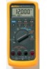
meter. Your Fluke 787 ProcessMeter™ (referred to as "the meter") is a handheld, battery-operated tool for measuring electrical parameters and supplying steady or ramping current to test process instruments. It has all the features of a digital multimeter, plus current output capability. Your meter - Fluke 787 | FE 787 Users Manual - Page 6
787 Users Manual Address correspondence to: Fluke Corporation P.O. Box 9090, Everett, WA 98206-9090 USA Fluke Europe B.V. P.O. Box 1186, 5602 BD Eindhoven The Netherlands Or visit us on the World Wide Web: www.fluke.com Safety Information The meter complies with IEC1010-1, ANSI/ISA S82.011994 - Fluke 787 | FE 787 Users Manual - Page 7
dust. • Use only a single 9V battery, properly installed in the meter case, to power the meter. • When servicing the meter, use only specified replacement parts. ProcessMeter Safety Information Caution To avoid possible damage to meter or to equipment under test: Disconnect the power and discharge - Fluke 787 | FE 787 Users Manual - Page 8
787 Users Manual Symbol c Table 1. International Symbols Meaning Alternating current Symbol Meaning Earth ground Direct current Fuse Alternating or direct current Conforms to European Union directives Refer to the manual for information about this feature. Conforms to relevant Canadian - Fluke 787 | FE 787 Users Manual - Page 9
various functions and features that you can use. Display Rotary Switch ProcessMeter How to Get Started 787 PROCESSMETER MIN MAX % STEP RANGE COARSE REL HOLD H FINE Hz mV V mA A OUTPUT mA V mA OFF OUTPUT 0-24mA SOURCE + SIMULATE + A mA COM V 0.44A (1A /30 sec) FUSED 30mA FUSED - Fluke 787 | FE 787 Users Manual - Page 10
. • Figure and Table 5 describe the functions of the pushbuttons. • Figure and Table 6 explain what all the elements of the display indicate. OUTPUT 0-24mA 1 SOURCE + SIMULATE + 3 A mA COM V 0.44A (1A /30 sec) FUSED 30mA FUSED CAT 1000V 2 4 Figure 2. Input/Output Jacks ee001f.eps 6 - Fluke 787 | FE 787 Users Manual - Page 11
ProcessMeter Getting Acquainted with the Meter Item A B C D Table 2. Input/Output Jacks Jack c A d mA Measurement Functions Source Current Function Input for current to 440 mA continuous. (1A for up to 30 seconds.) Fused with a 440 mA fuse. Output for dc current to 24 mA. Input for current - Fluke 787 | FE 787 Users Manual - Page 12
787 Users Manual 4 3 2 1 5 mV V V OFF 6 mA A OUTPUT mA mA Figure 3. Rotary Switch Positions for Measurements 8 ee002f.eps - Fluke 787 | FE 787 Users Manual - Page 13
ProcessMeter Getting Acquainted with the Meter Table 3. Rotary Switch Positions for Measurements No. Position Function(s) Pushbutton Actions A OFF Meter off only one range T for continuity BLUE D test F mA A L High test lead in Same as above, except there is only one range for each input jack - Fluke 787 | FE 787 Users Manual - Page 14
787 Users Manual mV V V OFF mA A OUTPUT mA mA 1 2 Figure 4. Rotary Switch Positions for mA Output ee008.eps 10 - Fluke 787 | FE 787 Users Manual - Page 15
ProcessMeter Getting Acquainted with the Meter Table 4. Rotary Switch Positions for mA Output No. Position Default Function Pushbutton Actions A OUTPUT Test leads in [ mA SOURCE: Source 0% mA Test leads in SIMULATE: Sink 0% mA % STEP X or W: Adjusts output up or down to the next 25% step - Fluke 787 | FE 787 Users Manual - Page 16
787 Users Manual No. A B 12 2 3 4 5 MIN MAX % STEP RANGE COARSE REL HOLD H FINE Hz 1 6 8 7 Pushbutton b U (BLUE) Figure 5. Pushbuttons ee003f.eps Table 5. Pushbuttons Function(s) Toggles the backlight Rotary switch in mA A Lposition and test lead plugged into c A jack: Toggles - Fluke 787 | FE 787 Users Manual - Page 17
ProcessMeter Getting Acquainted with the Meter Table 5. Pushbuttons (cont.) No. Pushbutton Function(s) C X Measuring: Selects a MIN, MAX, or AVG action (see pg. 18) M mA Output: Adjusts mA output up to the next higher 25% step % STEP D Z Measuring: Selects a fixed range (hold for 1 - Fluke 787 | FE 787 Users Manual - Page 18
787 Users Manual 67 8 9 5 4 3 2 1 11 12 Figure 6. Elements of the Display 14 10 ee004f.eps - Fluke 787 | FE 787 Users Manual - Page 19
with the Meter Table 6. Display No. Element Meaning A Percentage display Shows the mA measured value or output level in %, in a 0-20 mA or 4-20 mA scale (change scales with power-up option) B OUTPUT Lights when mA output (source or simulate) is active C D Lights in diode test function - Fluke 787 | FE 787 Users Manual - Page 20
787 Users Manual Table 6. Display (cont.) No. Element Meaning J mA, DC, mV, AC, Show the input or output units and multipliers associated with the numerals M or kΩ, kHz K Auto Range status indicators: 400100030 Auto means autoranging is on. The number plus the unit and - Fluke 787 | FE 787 Users Manual - Page 21
Most meter measurement functions have more than one range (see the Specifications). Being in the right range is important: • If the range is too low, the display shows OL (overload). • If the range is too high, the meter will not be displaying its most accurate measurement . ProcessMeter Measuring - Fluke 787 | FE 787 Users Manual - Page 22
787 Users Manual Testing Diodes To test a single diode: 1. Insert the red test lead into the Vjack and black test lead into the COM jack. 2. Set the rotary switch to O. 3. Press the BLUE pushbutton so that the D symbol is on the display. 4. Touch the red probe to the anode and the black probe to the - Fluke 787 | FE 787 Users Manual - Page 23
counter function). Press I to activate TouchHold. This feature allows you to take measurements in situations in which it is difficult to look at the display. The meter beeps and updates the display with each new stable reading. ProcessMeter Measuring Electrical Parameters Compensating for Test Lead - Fluke 787 | FE 787 Users Manual - Page 24
787 Users Manual Using the Current Output Functions The meter provides steady, stepped, and ramped current output for testing 0-20 mA and 4-20 mA current loops. You can choose source mode, in which the meter supplies the current, or simulate mode, in which the meter regulates current in an - Fluke 787 | FE 787 Users Manual - Page 25
787 PROCESSMETER MIN MAX % STEP RANGE COARSE REL HOLD H FINE Hz mV V mA A OUTPUT mA V mA OFF OUTPUT 0-24mA SOURCE + SIMULATE + A mA COM V 0.44A (1A /30 sec) FUSED 30mA FUSED CAT 1000V ProcessMeter Using the Current Output Functions 40 20 60 80 0 100 Figure 7. Sourcing - Fluke 787 | FE 787 Users Manual - Page 26
787 Users Manual Simulate Mode Simulate mode is so named because the meter simulates a current loop transmitter. Use simulate mode when an external dc voltage of 24 to 30V is in series with the current loop under test. Caution Set the rotary switch to one of the mA output settings BEFORE you connect - Fluke 787 | FE 787 Users Manual - Page 27
V Power Supply COM +24V 787 PROCESSMETER MIN MAX % STEP RANGE COARSE REL HOLD H FINE Hz mV V mA A OUTPUT mA V mA OFF OUTPUT 0-24mA SOURCE + SIMULATE + A mA COM V 0.44A (1A /30 sec) FUSED 30mA FUSED CAT 1000V ProcessMeter Using the Current Output Functions 40 20 60 80 0 100 - Fluke 787 | FE 787 Users Manual - Page 28
787 Users Manual Producing a Steady mA Output When the rotary switch is in the OUTPUT [ mA position, and the OUTPUT jacks are connected to an appropriate load, the meter produces a steady mA dc output. The meter begins sourcing or simulating 0%. Use the pushbuttons to adjust the current as shown in - Fluke 787 | FE 787 Users Manual - Page 29
display. When the impedance between the SOURCE jacks is low enough, the meter will resume sourcing. Note The COARSE and FINE adjustment pushbuttons described on the previous page are available when you are manually stepping the mA output. ProcessMeter Using the Current Output Functions Table 9. mA - Fluke 787 | FE 787 Users Manual - Page 30
787 Users Manual Step 0% 25% 50% 75% 100% 125% 120% Table 10. mA Step Values Value (for each span setting) 4 to 20 mA 0 to 20 mA 4.000 mA 0.000 mA 8.000 mA 5.000 mA 12.000 mA 10.000 mA 16.000 mA 15.000 mA 20.000 mA 20.000 mA 24.000 mA 24.000 mA Auto Ramping the mA Output Auto - Fluke 787 | FE 787 Users Manual - Page 31
you release the pushbutton after powering up the meter. The meter beeps to acknowledge the power-up option. ProcessMeter Power-Up Options Only the setting for Action Taken Toggles between 0 and 4 mA Disables beeper Disables the feature that turns off the meter power after 30 minutes of inactivity. - Fluke 787 | FE 787 Users Manual - Page 32
a Fluke Service Center. General Maintenance Periodically wipe the case with a damp cloth and detergent; do not use abrasives or solvents. Calibration Calibrate your meter once a year to ensure that it performs according to its specifications. Contact a Fluke Service Center for instructions. 28 - Fluke 787 | FE 787 Users Manual - Page 33
ProcessMeter Maintenance Holster with Flex-Stand bent Holster with Flex-Stand extended Holster with probe in clip Meter in holster face down for protection (Store Quick Reference Card under meter) Holster with Flex-Stand looped over wall Figure 9. Using the Holster and Flex-Stand Holster with - Fluke 787 | FE 787 Users Manual - Page 34
787 Users Manual Replacing the Battery ! Warning To avoid electrical shock, remove test leads from the meter before you open the battery door. Close and latch the battery door before you use the meter. Remove test leads from the meter before you open the battery door. Replace the battery as follows. - Fluke 787 | FE 787 Users Manual - Page 35
Gently lift the bottom of the front of the case (nearest the input/output jacks) until the top unsnaps from the rear half of the case. 5. Replace the blown fuse with the exact type specified: 440 mA 1000V fast-blow fuse, Fluke PN 943121. Both fuses are the same type. 6. Make sure the rotary switch - Fluke 787 | FE 787 Users Manual - Page 36
787 Users Manual If the Meter does not Work • Examine the case for physical damage. If there is damage, make no further attempt to use the meter, and contact a Fluke Service Center. • Check the battery, fuses, and test leads. • Review this manual to make sure you are using the correct jacks and - Fluke 787 | FE 787 Users Manual - Page 37
replacement fuse, 440 mA 1000V fast-blow, Fluke PN 943121. Note When servicing the meter, use only the replacement parts specified here. ProcessMeter Replacement Parts and Accessories Replacement parts and some accessories are shown in Figure 12 and listed in Table 13. Many more DMM accessories - Fluke 787 | FE 787 Users Manual - Page 38
top Case bottom Case screw Non-skid foot O-ring for input/output receptacle Battery door Battery door fasteners Keypad Standard test lead set Alligator clips for use with TL75 test lead set Industrial test lead set Product Overview Manual Users Manual (CD-ROM) Calibration Manual (not shown) Fluke - Fluke 787 | FE 787 Users Manual - Page 39
MP85 F2 F1 MP8 MP86 H2, 3, 4 BT1 H5, 6 ProcessMeter Replacement Parts and Accessories S1 TL20 (Option) Industrial Test Lead Set AC70A Alligator Clips TL75 Test Lead Set Product Overview Manual Holster CG81Y MP89, 90 MP92 CD-ROM (Users Manual) Figure 12. Replacement Parts ee015c.eps 35 - Fluke 787 | FE 787 Users Manual - Page 40
787 Users Manual Specifications All specifications apply from +18°C to +28°C unless stated otherwise. All specifications assume a 5 minute warmup period. The standard specification interval is 1 year. Note "Counts" - Fluke 787 | FE 787 Users Manual - Page 41
ProcessMeter Specifications DC Millivolts Measurement Range (mV dc) Resolution Accuracy (% of Reading + Counts) 400.0 0. 1 mV 0.1% + 1 AC Volts Measurement Range (ac) Resolution Accuracy, ±(% of Reading + Counts) 50 - Fluke 787 | FE 787 Users Manual - Page 42
787 Users Manual AC Current Measurement Range 45 Hz to 2 kHz Resolution Accuracy, ±(% of Reading + Counts) 1.000A (Note) 0.001A Note: 440 mA 000 mA 0.001 mA 1.000A (Note) 0.001A Note: 440 mA continuous, 1A 30 seconds maximum Overload protection: 440 mA, 1000V fast-blow fuse 0.05 - Fluke 787 | FE 787 Users Manual - Page 43
kΩ 400.0 kΩ 0.1 kΩ 4.000 MΩ 0.001 MΩ 40.00 MΩ 0.01 MΩ Overload protection: 1000V Open circuit voltage: - Fluke 787 | FE 787 Users Manual - Page 44
787 Users Manual Frequency Counter Accuracy Range Resolution 199.99 Hz 0.01 Hz 1999.9 Hz 0.1 Hz 19.999 kHz 0.001 kHz Display updates 3 times/second at >10 Hz Frequency Counter Sensitivity Input Range 1 V 4 V 40 V 400 V 1000 V * Usable 0.5 Hz to 20 kHz with reduced sensitivity. Accuracy - Fluke 787 | FE 787 Users Manual - Page 45
Overload protection: 1000V rms DC Current Output Source mode: Span: 0 mA or 4 mA to 20 mA, with overrange to 24 mA Accuracy: 0.05% of span Compliance voltage: 12V with battery voltage >8.5V Simulate Mode: Span: 0 mA or 4 mA to 20 mA, with overrange to 24 mA Accuracy: 0.05% of span Loop voltage - Fluke 787 | FE 787 Users Manual - Page 46
787 Users Manual Vibration: Random 2g, 5 to 500 Hz Shock: 1 meter drop test Water and dust protection: Complies with IEC529 IP52 (normal operating vacuum used for dust test) Safety: Complies with IEC1010-1, ANSI/ISA S82.011994 - Fluke 787 | FE 787 Users Manual - Page 47
, 17 -B- Battery Replacement, 30 Buttons, 12 -C- Calibrating the meter, 28 Compensating for test lead resistance, 19 Composite Signals, 17 Index Current output Compliance, 24 Load impedance, 24 Ramping, auto, 26 Simulating a transmitter, 22 Sourcing, 20 Span (4-20 mA or 0-20 mA), 22 Steady, 24 - Fluke 787 | FE 787 Users Manual - Page 48
787 Users Manual -F- Flex-Stand, 28 Freezing a reading (TouchHold), 19 Fuse, checking and replacing, 31 -H- Holster, 28 -I- Input/Output jacks, 7 -J- Jacks, 7 -K- Knob positions, 9, 11 -L- Loop supply, external, 22 44 M- mA output. See Current output Mailing address for Fluke, 2 Maintenance, 28 - Fluke 787 | FE 787 Users Manual - Page 49
reading, 19 Rotary switch positions, 9, 11 -S- Safety information, 2 Screen, 15 Service and sales, 1 Settings, 27 Simulating. See Current output Index (continued) Sourcing. See Current output Specifications, 36 Switch positions, 9, 11 Symbols, international, 4 -T- Telephone numbers, 1 TouchHold - Fluke 787 | FE 787 Users Manual - Page 50
787 Users Manual 46
-
 1
1 -
 2
2 -
 3
3 -
 4
4 -
 5
5 -
 6
6 -
 7
7 -
8
-
9
-
10
-
11
-
12
-
13
-
14
-
15
-
16
-
17
-
18
-
19
-
20
-
21
-
22
-
23
-
24
-
25
-
26
-
27
-
28
-
29
-
30
-
31
-
32
-
33
-
34
-
35
-
36
-
37
-
38
-
39
-
40
-
41
-
42
-
43
-
44
-
45
-
46
-
47
-
48
-
49
-
50
 |
 |

®
787
ProcessMeter
Users Manual
April 1997, Rev.3, 12/01
© 1997, 1898, 2000, 2001 Fluke Corporation, All rights reserved. Printed in U.S.A.
All product names are trademarks of their respective companies.