Foxconn P67A-S User manual
Foxconn P67A-S Manual
 |
View all Foxconn P67A-S manuals
Add to My Manuals
Save this manual to your list of manuals |
Foxconn P67A-S manual content summary:
- Foxconn P67A-S | User manual - Page 1
P67A Series Motherboard User's Manual - Foxconn P67A-S | User manual - Page 2
property of their respective owners. Version: User's Manual V1.1 for P67A Series motherboard. Symbol description: ! Caution: refers to important information that can help you to use motherboard better, and tells you how to avoid problems. WARNING! Warning: indicating a potential risk of hardware - Foxconn P67A-S | User manual - Page 3
HAI PRECISION INDUSTRY COMPANY LTD 66 , CHUNG SHAN RD., TU-CHENG INDUSTRIAL DISTRICT, TAIPEI HSIEN, TAIWAN, R.O.C. declares that the product Motherboard P67A/P67A-S is in conformity with (reference to the specification under which conformity is declared in accordance with 89/336 EEC-EMC Directive - Foxconn P67A-S | User manual - Page 4
Party: Address: Telephone: Facsimile: FOXCONN P67A/P67A-S PCE Industry Inc. 458 E. Lambert Rd. Fullerton, CA 92835 714-738-8868 714-738-8838 Equipment Classification: Type of Product: Manufacturer: Address: FCC Class B Subassembly Motherboard HON HAI PRECISION INDUSTRY COMPANY LTD - Foxconn P67A-S | User manual - Page 5
to avoid damage to the motherboard and CPU due to high temperature. Never turn on the computer if the CPU fan is not properly installed. ■ We cannot guarantee that your system can operate normally when your CPU is overclocked. Normal operation depends on the overclocking capac- ity of your - Foxconn P67A-S | User manual - Page 6
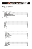
40 Save & Exit 41 Chapter 4 CD Instruction Utility CD content 43 Install driver and utility 44 FOX ONE Main Page 47 CPU Control 51 Frequency Control 53 Limit Setting 54 Voltage Control 56 Fan Control 57 FOX LiveUpdate Local Update 58 Online Update 60 Configure 63 About & Help 65 FOX - Foxconn P67A-S | User manual - Page 7
RAID Configuration Introduction 71 Intel® Matrix Storage Manager 73 Create a RAID Driver Diskette 74 BIOS Configuration 76 Create RAID in BIOS 76 Install a New Windows XP 105 Technical Support : Website : http://www.foxconnchannel.com Support Support Website : http://www.foxconnsupport - Foxconn P67A-S | User manual - Page 8
Foxconn P67A Series motherboard. Foxconn products are engineered to maximize computing power, providing only what you need for break-through performance. With advanced overclocking capability and a range of connectivity features for today multi-media computing requirements, P67A/P67A-S enables - Foxconn P67A-S | User manual - Page 9
Product Specifications 1 CPU Support LGA1155 for Intel Sandybridge series CPU Support CPU TDP 95W/92W/79W PWM with VRM heatink For the latest CPU information, please visit: http://www.foxconnsupport.com/cpusupportlist.aspx Chipset Intel® P67 Memory 4 x 240-pin DDR3 DIMMs Support up to 32GB - Foxconn P67A-S | User manual - Page 10
ports 2 x USB 3.0 ports (P67A-S) 1 x RJ-45 LAN port 8-channel Audio ports Hardware Monitor System voltage detection CPU/System temperature detection CPU/System fan speed detection CPU overheating warning CPU/System fan speed control PCI Express x1 Support 250MB/s (500MB/s concurrent - Foxconn P67A-S | User manual - Page 11
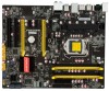
Connectors 13. Chassis Intrusion Alarm Header 14. Chipset: Intel® P67 15. IrDA Connector 16. SYS_FAN1/2 Header 17. IDE Connector 18. 24-pin ATX Power Connector 19. DDR3 DIMM Slots 20. CPU_FAN Header 21. LGA1155 CPU Socket Note : The above motherboard layout is for reference only, please refer to - Foxconn P67A-S | User manual - Page 12
this port for USB devices such as an USB keyboard/mouse, USB printer, USB flash drive and etc. But you need to install the USB 3.0 driver in the Driver CD before using it. (P67A don't support USB 3.0) 3. Optical S/PDIF Out Port This port provides digital audio out to an external audio system that - Foxconn P67A-S | User manual - Page 13
1 7. Audio Ports For the definition of each audio port, please refer to the table below : Port 2-channel 4-channel 5.1-channel 7.1-channel Blue Line In Line In Line In Line In Green Line Out Front Speaker Out Front Speaker Out Front Speaker Out Pink Microphone In Microphone In - Foxconn P67A-S | User manual - Page 14
the following information : ■ Install the CPU and CPU Cooler ■ Install the Memory ■ Install an Expansion Card ■ Install other Internal Connectors ■ Jumpers Please visit the following website for more supporting information about your motherboard. CPU Support List: http://www.foxconnsupport.com - Foxconn P67A-S | User manual - Page 15
is optimized for HT Technology ■ A BIOS that supports HT Technology and has it enabled Install the CPU Locate the alignment keys on the motherboard CPU socket and the notches on the CPU. LGA1155 CPU Socket Alignment Key Pin-1 corner of the CPU Socket Notch LGA1155 CPU Pin-1 triangle marking of - Foxconn P67A-S | User manual - Page 16
Lift the metal cover on the CPU socket. 3. Remove protective socket cover. 4. Check pin one marking (triangle) with the pin one corner of the CPU socket, align the CPU notches with the socket alignment keys and gently put the CPU onto the socket. 5. When CPU is properly seated, replace the metal - Foxconn P67A-S | User manual - Page 17
, the push pin should be fixed as depicted in the picture. 4. Attach the 4-wire CPU cooler connector to the CPU FAN header on the motherboard . 3 2 1 Release bolts of CPU cooler from motherboard : 1.Turning the push pin (bolt) along with the direction of arrow (counterclockwise). 2. Pull the - Foxconn P67A-S | User manual - Page 18
direction. If you are unable to insert the memory, switch the direction. Dual Channel Memory Configuration This motherboard provides four DDR3 memory sockets and supports Dual Channel Technology. When memory is installed, the BIOS will automatically check the memory in your system. Four DDR3 memory - Foxconn P67A-S | User manual - Page 19
damage to the memory module. Be sure to install DDR3 DIMMs on this motherboard. Notch If you take a look at front side of memory module, it your memory modules into the sockets. Step 1: Spread the clips at both ends of the memory socket. Place the memory module onto the socket, then put your fingers - Foxconn P67A-S | User manual - Page 20
2 2-3 Install an Expansion Card ! ■ Make sure the motherboard supports the expansion card. Carefully read the manual that came with your expansion card. ■ Always turn off the computer and unplug the power cord from the power outlet before installing an expansion card to prevent hardware damage. PCI - Foxconn P67A-S | User manual - Page 21
power supply cable and pins are properly aligned with the connector on the motherboard. Firmly plug the power supply cable into the connector and make sure it 8-pin ATX 12V power supply to PWR2 and provides power to the CPU. 51 +12V GND 84 PWR2 Pin # 1 2 3 4 Definition GND GND GND GND Pin # - Foxconn P67A-S | User manual - Page 22
rear panel, this product also provides three 10-pin USB headers on its motherboard. By connecting through USB cables with them, user can quickly expand another eight connector is used to connect with SATA Hard Disk or CD devices which support this feature. 1 GND TX+ TX- GND RXRX+ GND The current - Foxconn P67A-S | User manual - Page 23
SW PWR-SW NC EMPTY 9 10 FP1 COM Connector : COM1 This motherboard supports one serial RS232 COM port for legacy compatibility. User must purchase another fan headers on this motherboard. The fan speed can be controlled and monitored in "PC Health Status" section of the BIOS Setup. These fans - Foxconn P67A-S | User manual - Page 24
of this connector. If eventually the chassis is closed, the system will send a message out. INTRUDERJ 1 INTR GND IrDA Connector : IR/CIR This connector supports infrared wireless trans-mitting and receiving device. 12 +5V EMPTY EMPTY GND EMPTY 9 10 IR/CIR +5VSB CIRRX GND CIRTX EMPTY 17 17 - Foxconn P67A-S | User manual - Page 25
ESD (Electrical Static Discharge) problem. Jumper 1 Diagram 1 1 Definition 1-2 2-3 Description Set Pin 1 and Pin 2 closed Set Pin 2 and Pin 3 closed Clear CMOS Jumper: CLR_CMOS The motherboard uses CMOS RAM to store the basic hardware information (such as BIOS data, date, time information - Foxconn P67A-S | User manual - Page 26
ME Jumper: MFG This motherboard uses MFG jumper to enable or disable Intel® Management Engine function. Intel® Management Engine (ME) is an embedded microcontroller located in Intel chipset. It provides latest IT management features such as Intel® AMT, that allows to improve management of corporate - Foxconn P67A-S | User manual - Page 27
CMOS settings. This chapter includes the following information : ■ Enter BIOS Setup ■ Main ■ Advanced ■ Chipset ■ Boot ■ Power ■ Health ■ Security ■ Save & Exit Since BIOS could be updated some other times, the BIOS information described in this manual is for reference only. We do not guarantee the - Foxconn P67A-S | User manual - Page 28
It displays the basic system configuration, such as CPU Name, memory size, system date, time and problem if you have more memory or I/O cards installed. It means, if your system loading is heavy, set to optimal default may sometimes come out an unstable system. What you need now is to adjust BIOS - Foxconn P67A-S | User manual - Page 29
Date elements. Access Level Administrator Model Name ME Version BIOS Version Build Date and Time P67A/P67A-S 7.0.0.1135 A46F1013 10/21/2010 09:21:20 Halt On All, but keyboard] CPU Brand Name: Genuine Intel(R) CPU 0 @ 2 .40GHz Total Memory MAC Address 2048 MB (DDR3 1333) 00-00-00-00-0D-00 - Foxconn P67A-S | User manual - Page 30
halt. [No Errors]: No error can result in system halt. [All, but keyboard]: All errors but keyboard can result in system halt. ► CPU Brand Name It displays the current CPU name. ► Total Memory This item displays the total memory size. The size is depending on how many memory modules are installed in - Foxconn P67A-S | User manual - Page 31
Values F3: Optimized Defaults F4: Save & Exit ESC: Exit Version 2.02.1205. Copyright (C) 2010 American Megatrends, Inc. ► Fox Control Center/CPU Configuration/Performance Tuning/SATA/USB Configuration/ Onboard Devic Configuration Press to go to relative submenu. Fox Control Center Aptio - Foxconn P67A-S | User manual - Page 32
. Advanced CPU Configuration Genuine Intel(R) CPU 0 @ 2.40GHz EMT64 Supported Processor Speed 1600 MHz CPU ID 206a2 Microcode Revision 26 Processor Cores 2 Intel HT Technology Supported C1E Support Hyper-threading Execute Disable Bit Intel Virtualization Technology CPU C6 - Foxconn P67A-S | User manual - Page 33
Aptio Setup Utility - C opyright (C) 2010 American Megatrends, Inc. Advanced Non Turbo Ratio Override 2255 Host Clock Override(1/100 MHz) 10000 CPU Voltage (1/10000 Volt) 0 Power Limit 1 Value (Watt) 95 Power Limit 2 Switch [Enabled] Power Limit 2 Value 118 EIST Enabled] Turbo - Foxconn P67A-S | User manual - Page 34
decreased average power consumption and decreased average heat production. There are some system requirements must be met, including CPU, chipset, motherboard, BIOS and operation system. Please refer to Intel Website for more information. ► Turbo Mode This item is used to set the mode of the Turbo - Foxconn P67A-S | User manual - Page 35
read CAS_L is asserted depends on the memory clock frequency. The value that BIOS programs into the memory controller is a function of the target clock frequency. The target clock frequency is determined from the supported CAS latencies at given clock frequencies of each DIMM. ► Row Precharge Time - Foxconn P67A-S | User manual - Page 36
American Megatrends, Inc. Advanced USB Configuration USB Devices: 2 Hubs Enabled/Disabled All USB Devices All USB Devices Legacy USB Support [Enabled] [Enabled] → ← : Select Screen ↑ ↓ : Select Item Enter: Select +/-: Change Opt. F1: General Help F2: Previous Values F3: Optimized - Foxconn P67A-S | User manual - Page 37
. [Disabled]: This option will keep USB devices available only for EFI applications. [Auto]: This option will disable the legacy support if no USB devices are connected. Onboard Device Configuration Aptio Setup Utility - C opyright (C) 2010 American Megatrends, Inc. Advanced Onboard Device - Foxconn P67A-S | User manual - Page 38
3 Super IO Configuration Aptio Setup Utility - C opyright (C) 2010 American Megatrends, Inc. Advanced Super IO Configuration Super IO Chip IT8728 Enable or Disable Serial Port (COM) Serial Port 0 Configuration Serial Port Device Settings Change Settings Device Mode [Enabled] IO=3F8h; - Foxconn P67A-S | User manual - Page 39
. North Bridge Aptio Setup Utility - C opyright (C) 2010 American Megatrends, Inc. Chipset Memory Information VT-d Enabled/Disable Total Memory 2048 MB (DDR3 1333) Memory Slot1 Memory Slot2 Memory Slot3 Memory Slot4 0 MB (DDR3 1333) 2048 MB (DDR3 1333) 0 MB (DDR3 1333) 0 MB (DDR3 - Foxconn P67A-S | User manual - Page 40
1/2/3/4 These items display the memory size installed on each slot. ► VT-d This item is used to enable or disable the VT-d feature. Intel® Virtualization Technology for Directed I/O (VT-d) can help end users improve security and reliability of the systems and also improve performance of I/O devices - Foxconn P67A-S | User manual - Page 41
Send ICC Lock Registers Set Profile Set Profile Index ▶ ICC OverClocking [Enabled] [Enabled] [Enabled] [Enabled] 0 → ← support. ► Set Profile Index This item is used to set the profile index. it only have one ICC Profile, so it always showed 0 when ICC set profile enable. ► ICC OverClocking - Foxconn P67A-S | User manual - Page 42
user can't change the setting. [DIV-1NS]: Clock 1NS not support spread spectrum. IGFX clock setting if support IGFX. But this clock is not used. Only display the default setting and user can't change the setting. [DIV-2NS]: Clock 2NS not support spread spectrum. The clock is used for BCLK, DMI and - Foxconn P67A-S | User manual - Page 43
3 Boot Aptio Setup Utility - C opyright (C) 2010 American Megatrends, Inc. Main Advanced Chipset Boot Power Health Security Save & Exit Boot Configuration Bootup Numlock State [On] Select the keyboard NumLock state Quiet Boot [Enabled] CSM16 Module Version 07.63 Boot Option - Foxconn P67A-S | User manual - Page 44
. In this state, no system context is lost (CPU or chip set) and hardware maintains all system context. the lowest power, longest wake latency sleeping state supported by ACPI. In order to reduce power to allow for initial boot operations within the BIOS to distinguish whether or not the boot is - Foxconn P67A-S | User manual - Page 45
state. ► Resume by PCI PME This item is used to enable/disable the PCI card to generate a wake up. ► Resume by PCIE PME This item is used to be cut off in S5 suspend mode in order to reduce the power consumption of motherboard. Enabled: S1/S3/S4 is normal, S5 wake up only by pressing the power - Foxconn P67A-S | User manual - Page 46
automatically by the system. ► System Fan 1 Speed This item shows the current North Bridge Fan speed detected automatically by the system. ► CPU Vcore/DRAM Voltage/+12V SYS/+5V SYS/VBAT These items show the Current CPU Ccore/DRAM/+12V SYS/+5V SYS/VBAt voltage detected automatically by the system - Foxconn P67A-S | User manual - Page 47
3 Security Aptio Setup Utility - C opyright (C) 2010 American Megatrends, Inc. Main Advanced Chipset Boot Power Health Security Save & Exit Password Description If ONLY the Administrator's password is set, then this only limits access to Setup and is only asked for when entering Setup. - Foxconn P67A-S | User manual - Page 48
, select [No] or to return to the main menu. ► Restore Defaults Optimal defaults are the best settings of this motherboard. Always load the Optimal defaults after updating the BIOS or after clearing the CMOS values. Select this option and press Enter, it will pop out a dialogue box to let you - Foxconn P67A-S | User manual - Page 49
The utility CD that came with the motherboard contains useful software and several utility drivers that enhance the motherboard features. This chapter includes the following information: ■ Utility CD content ■ Install driver and utility ■ FOX ONE ■ FOX LiveUpdate ■ FOX LOGO ■ FOX DMI ■ Browser - Foxconn P67A-S | User manual - Page 50
E. Intel Management Engine F. USB 3.0 Driver 2. Software Utilities Use these options to install additional software programs. FOX ONE is a very powerful user interface program which allows you to change your system setting without going to BIOS. Some auto features help user to improve (or overclock - Foxconn P67A-S | User manual - Page 51
, or you can click on each individual driver to install it manually. Manual Installation Step by Step Automatic Installation by One Click Drop to System Tray Exit the program Click to visit Select to Install Select to Foxconn's Utilities Install Drivers website Browse CD View the Utility Help - Foxconn P67A-S | User manual - Page 52
4 2. Install Utility Use these options to install additional software programs. 3. Utility Help Click this button to view the utility(FOX ONE, FOX LiveUpdate, FOX LOGO, FOX DMI) help manual. 45 45 - Foxconn P67A-S | User manual - Page 53
supported. ■ Voltage Monitoring is supported only in FOX ONE Premium & Deluxe products. ■ Fox Intelligent Stepping is supported only in FOX ONE Deluxe products. Supporting ONE program, the system parameters (such as CPU clock, voltage...etc.) are controlled by BIOS settings. After you run FOX ONE, - Foxconn P67A-S | User manual - Page 54
1. Main Page Show CPU Information Toolbar Alert Lamp 4 Switch Button Skin Button Exit Minimum Configuration Homepage Monitor Frequency/Voltage/Fan speed/Temperature value Toolbar Use the toolbar to navigate - Foxconn P67A-S | User manual - Page 55
button to drop the FOX ONE to Windows system tray located at the lower right corner of your screen. Homepage Click this button to visit Foxconn motherboard website : http://www.foxconnchannel.com 48 48 - Foxconn P67A-S | User manual - Page 56
value is 1 second. 2). Simple Mode : To select which message of system settings are to be displayed in the Simple Mode. Messages such as CPU frequency, voltage...etc., they can be displayed one by one in Simple Mode. 3). F.I.S. Calibration (FOX Intelligent Stepping, Optional) This function will re - Foxconn P67A-S | User manual - Page 57
collected, it will ask you to restart your computer now. Later on, when the FOX ONE program is activated, and F.I.S. feature (in CPU Page) is also enabled, FOX ONE will automatically adjust your CPU clock according to your system loadings. (Loadings are like Power Gaming, Data Mining...etc.) 50 50 - Foxconn P67A-S | User manual - Page 58
This page lets you select (or overclock) CPU clock to meet the current performance level of the system. The fastest and suitable CPU clock running for current system can be calculated by FOX ONE automatically or manually input by yourselves. Manual : You can press the up/down button to adjust - Foxconn P67A-S | User manual - Page 59
of your system to restart the computer. Run FOX ONE program again, it will inform you the previous test found that 255MHz is the recommended CPU clock for your system. Click Yes to apply it to your system. Now, your system is running at - Foxconn P67A-S | User manual - Page 60
in the FIS Calibration option of Configuration menu. Select Auto, CPU will automatically adjust its clock according to current system loading. 4 and PCI Express frequencies by manual. Go to Freq. page Close this page Select the option you want to set Adjust by manual Reset the changes Apply the - Foxconn P67A-S | User manual - Page 61
limit temperature and enable the alert function. Go to Limit Show current CPU Setting page temperature value Enable alert function when the CPU temperature is higher than high limit value Show current high limit value of the CPU temperature 4 Set high limit by dragging the lever 4.2 Limit Setting - Foxconn P67A-S | User manual - Page 62
runs slower than the low limit rpm value Show current low limit rpm value of CPU fan 4 Set low limit rpm by dragging the lever 4.4 Limit Setting - System Fan This page lets you to set system fan low limit rpm and - Foxconn P67A-S | User manual - Page 63
low limit rpm value of FAN1 fan Set low limit rpm by dragging the lever 5. Voltage Page - Voltage Control (Optional) This page lets you set CPU voltage, memory voltage and North Bridge voltage manually. CPU voltage can be stepped up/down by a unit of 12.5mV, while memory is 0.05V/step, and North - Foxconn P67A-S | User manual - Page 64
4 6. Fan Page - Fan Control This page lets you enable Smart Fan function or set the fan speed by manual. When Smart Fan is selected, you must use a 4-pin CPU cooler in your system. Go to Fan page Enable or disable smart fan function Set fan speed by dragging the lever Apply the changes 57 57 - Foxconn P67A-S | User manual - Page 65
4 CAUTION FOX LiveUpdate FOX LiveUpdate is a useful utility to backup and update your system BIOS, drivers and utilities by local or online. Supporting Operating Systems : ■ Windows 2000 ■ Windows XP (32-bit and 64-bit) ■ Windows 2003 (32-bit and 64-bit) ■ Windows Vista (32-bit and 64-bit) ■ - Foxconn P67A-S | User manual - Page 66
guide you to load a local BIOS file to finish the operation. You must remember from which directory to load your new BIOS file (with an extension of ".BIN" for Award BIOS, ".ROM" for AMI BIOS) before the setup wizard starts. CAUTION ! FOX LiveUpdate can automatically backup old BIOS before update - Foxconn P67A-S | User manual - Page 67
the wizard to finish the update operation. Click here 4 Current information Select BIOS to update Search new BIOS from Internet Browse detailed information Update BIOS Close the window 2-2 Online Update - Update Driver This page lets you update your system drivers from Internet. Click "start - Foxconn P67A-S | User manual - Page 68
the driver to update Browse detailed information Install the selected driver Close the window 2-3 Online Update - Update Utility This page lets you update utilities from Internet. Click "start", it will search the new utilities from Internet. Then follow the wizard to finish the update operation - Foxconn P67A-S | User manual - Page 69
4 2-4 Online Update - Update All This page lets you update your system drivers from Internet. Click "start", it will search all new BIOS/drivers/utilities from Internet. Then follow the wizard to finish the update operation. Click here Current information Search all new BIOS/ drivers/utilities from - Foxconn P67A-S | User manual - Page 70
3. Configure 3-1 Configure - option This page lets you set auto search options. After you enable the auto search function, FOX LiveUpdate will start its searching from Internet and if any qualified item found, it will pop out a message on the task bar to inform you to do the next step. Click here - Foxconn P67A-S | User manual - Page 71
the new version. Prompt you to install the new FOX LiveUpdate 3-2 Configure - System This page lets you set the location of download files and auto backup BIOS, determine if the FOX LiveUpdate can auto run when the system starts up. Click here Set the location of download files or auto - Foxconn P67A-S | User manual - Page 72
protective, and you must make sure the flash process is continuous and without any interruption. Click here Select which BIOS ROM to flash(Only available to motherboard with backup BIOS ROM ) Select to flash Boot Block Select to clear CMOS Apply the changes Reset to default value ! We recommend - Foxconn P67A-S | User manual - Page 73
: Main Page Main screen Backup Change Delete Exit Minimize Website About WARNING! When you change Logo or delete current Logo, the system will flash BIOS file automatically. During this time, please DO NOT shut down the application and the system, or the motherboard will be damaged seriously. 66 - Foxconn P67A-S | User manual - Page 74
three DMI data formats : Report, Data Fields and Memory Dump. With DMI information, system maker can easily analyze and troubleshoot your motherboard if there is any problem occurred. Supporting Operating Systems : ■ Windows 2000 ■ Windows XP (32-bit and 64-bit) ■ Windows 2003 (32-bit and 64-bit - Foxconn P67A-S | User manual - Page 75
4 Browser Configuration Utility Browser Configuration Utility is a browser search engine of Yahoo. We provide it to you for various choice. Supporting Operating Systems : ■ Windows XP (32-bit and 64-bit) ■ Windows Vista (32-bit and 64-bit) ■ Windows 7 (32-bit and 64-bit) Using Browser Configuration - Foxconn P67A-S | User manual - Page 76
This chapter will include the following information : ■ RAID Configuration Introduction ■ Intel® Matrix Storage Manager ■ Create a RAID Driver Diskette ■ BIOS Configuration ■ Create RAID in BIOS ■ Install a New Windows XP - Foxconn P67A-S | User manual - Page 77
AHCI. 3. Follow 5-3 to create RAID in BIOS. 4. Follow 5-4 to Install Windows Operating System. What kinds of hardware and software you need here : 1. A floppy drive. 2. A CD-ROM drive. 3. Several SATA hard disks. 4. A RAID driver diskette. 5. A motherboard driver CD. 6. Windows XP or Vista Install - Foxconn P67A-S | User manual - Page 78
I/O (input/output) performance, or both. The motherboard comes with the Intel® PCH. The following RAID configurations are provided for users viewers. The configuration affects reliability and performance in different ways. The problem with using more disks is that it is more likely that one - Foxconn P67A-S | User manual - Page 79
size can be set from 4KB to 128KB. RAID 0 does not support fault tolerance. RAID 1 (Mirror) RAID 1 writes duplicate data size for Recovery, but you must select a sync mode to update the volume. Comparison Table : Solution RAID0 RAID1 RAID5 Hard % Data backup Limited budget Excellent Unlimited budget - Foxconn P67A-S | User manual - Page 80
end of the SATA cable to motherboard's SATA connector, and the other end to SATA hard disk. 3. Connect SATA power cable to the power connector of SATA hard disk. WARNING! ■ Both AHCI and RAID modes need to install Intel® Matrix Storage Manager driver. ■ Set SATA mode in BIOS to AHCI, you can skip - Foxconn P67A-S | User manual - Page 81
BIOS to either AHCI or RAID first. You also need to create a RAID driver diskette for use in installing your Windows XP system. Windows Vista has native RAID driver a 32-bit XP system. Use Windows explorer, and go to CD:\Driver\ Intel\RAID\Floppy\32bit, click on RaidTool icon to start the creation. - Foxconn P67A-S | User manual - Page 82
files. Later, when in the process of installing Windows XP in your RAID system, it will ask you to use this floppy diskette to provide driver for additional specific devices, for example, a RAID device. 10. Install Serial ATA Hard Disks : 10-1. Shut down your computer. 10-2. Install SATA hard disks - Foxconn P67A-S | User manual - Page 83
When BIOS is restarted, it will display a message asking you to press + keys simultaneously to enter the main menu of Intel® Matrix Storage Manager Option ROM Utility. Press the + to enter Configuration Utility. Intel(RIn) tMela(Rtr)ixRSatpoirdagSetoMraagneaTgeecrhonpotilongyR - Foxconn P67A-S | User manual - Page 84
(RIn) tMela(Rtr)ixRSatpoirdagSetoMraagneaTgeecrhonpotilongyR-OOMptvio5n.0R.0O.1M01-11I0C.0H.90R.10w3R2AID5 Copyright(C) 2003-1004 Intel Corporation.AlAl Rll iRgihgthstsReRseesrevrevde.d. [ CREATE VOLUME MENU ] Name: TryRAID0 RAID Level: RAID0(Stripe) Disks: Select Disks Strip Size: 128KB - Foxconn P67A-S | User manual - Page 85
selected. Here, we select two 149.0GB hard disks as an example. Press key to finish the selection. Intel(RIn) tMela(Rtr)ixRSatpoirdagSetoMraagneaTgeecrhonpotilongyR-OOMptvio5n.0R.0O.1M01-11I0C.0H.90R.10w3R2AID5 CCooppyyrriigghhtt((CC)) 22000033--1004 IInntteell CCoorrppoorraattiioonn.AlAl - Foxconn P67A-S | User manual - Page 86
first volume. Later, we will also describe how the second volume is generated. Input 150GB, and press . Intel(RIn) tMela(Rtr)ixRSatpoirdagSetoMraagneaTgeecrhonpotilongyR-OOMptvio5n.0R.0O.1M01-11I0C.0H.90R.10w3R2AID5 CCooppyyrriigghhtt((CC)) 22000033--1004 IInntteell CCoorrppoorraattiioonn - Foxconn P67A-S | User manual - Page 87
9. Press to create the volume and return to the main menu, a 150GB RAID0 system is normally configured. Intel(RIn) tMela(Rtr)ixRSatpoirdagSetoMraagneaTgeecrhonpotilongyR-OOMptvio5n.0R.0O.1M01-11I0C.0H.90R.10w3R2AID5 CCooppyyrriigghhtt((CC)) 22000033--1004 IInntteell CCoorrppoorraattiioonn.AlAl - Foxconn P67A-S | User manual - Page 88
(RIn) tMela(Rtr)ixRSatpoirdagSetoMraagneaTgeecrhonpotilongyR-OOMptvio5n.0R.0O.1M01-11I0C.0H.90R.10w3R2AID5 Copyright(C) 2003-1004 Intel Corporation.AlAl Rll iRgihgthstsReRseesrevrevde.d. [ CREATE VOLUME MENU ] Name: TryRAID0-1 RAID Level: RAID0(Stripe) Disks: Select Disks Strip Size: 128KB - Foxconn P67A-S | User manual - Page 89
then goes to "Disks" item. Press to display the hard disks list for this RAID0 second volume system. Intel(RIn) tMela(Rtr)ixRSatpoirdagSetoMraagneaTgeecrhonpotilongyR-OOMptvio5n.0R.0O.1M01-11I0C.0H.90R.10w3R2AID5 CCooppyyrriigghhtt((CC)) 22000033--1004 IInntteell CCoorrppoorraattiioonn.AlAl - Foxconn P67A-S | User manual - Page 90
Good general purpose strip size. 128K - Best performance for most desktops and workstations . The default value is 128K. Press . Intel(RIn) tMela(Rtr)ixRSatpoirdagSetoMraagneaTgeecrhonpotilongyR-OOMptvio5n.0R.0O.1M01-11I0C.0H.90R.10w3R2AID5 CCooppyyrriigghhtt((CC)) 22000033--1004 IInntteell - Foxconn P67A-S | User manual - Page 91
volume ? (Y/N) : Press to create the volume and return to the main menu. Two RAID0 volumes were configured. Intel(RIn) tMela(Rtr)ixRSatpoirdagSetoMraagneaTgeecrhonpotilongyR-OOMptvio5n.0R.0O.1M01-11I0C.0H.90R.10w3R2AID5 CCooppyyrriigghhtt((CC)) 22000033--1004 IInntteell CCoorrppoorraattiioonn - Foxconn P67A-S | User manual - Page 92
(RIn) tMela(Rtr)ixRSatpoirdagSetoMraagneaTgeecrhonpotilongyR-OOMptvio5n.0R.0O.1M01-11I0C.0H.90R.10w3R2AID5 Copyright(C) 2003-1004 Intel Corporation.AlAl Rll iRgihgthstsReRseesrevrevde.d. [ CREATE VOLUME MENU ] Name: VTroyluRmAeID01 RAID Level: RAID0(Stripe) Disks: Select Disks Strip Size - Foxconn P67A-S | User manual - Page 93
to dispaly the hard disks list for this RAID1 system. Intel(RIn) tMela(Rtr)ixRSatpoirdagSetoMraagneaTgeecrhonpotilongyR-OOMptvio5n.0R.0O.1M01-11I0C.0H disks. Press key to finish the selection. Intel(RIn) tMela(Rtr)ixRSatpoirdagSetoMraagneaTgeecrhonpotilongyR-OOMptvio5n.0R.0O.1M01-11I0C.0H - Foxconn P67A-S | User manual - Page 94
sure you want to create this volume ? (Y/N) : Press to create the volume and return to the main menu. Intel(RIn) tMela(Rtr)ixRSatpoirdagSetoMraagneaTgeecrhonpotilongyR-OOMptvio5n.0R.0O.1M01-11I0C.0H.90R.10w3R2AID5 CCooppyyrriigghhtt((CC)) 22000033--1004 IInntteell CCoorrppoorraattiioonn.AlAl - Foxconn P67A-S | User manual - Page 95
(RIn) tMela(Rtr)ixRSatpoirdagSetoMraagneaTgeecrhonpotilongyR-OOMptvio5n.0R.0O.1M01-11I0C.0H.90R.10w3R2AID5 Copyright(C) 2003-1004 Intel Corporation.AlAl Rll iRgihgthstsReRseesrevrevde.d. [ CREATE VOLUME MENU ] Name: VTroyluRmAeID010 RAID Level: RAID0(Stripe) Disks: Select Disks Strip Size - Foxconn P67A-S | User manual - Page 96
Down arrow key to select the desired strip size when entering "Strip Size" menu. The default value is 64K. Intel(RIn) tMela(Rtr)ixRSatpoirdagSetoMraagneaTgeecrhonpotilongyR-OOMptvio5n.0R.0O.1M01-11I0C.0H.90R.10w3R2AID5 CCooppyyrriigghhtt((CC)) 22000033--1004 IInntteell CCoorrppoorraattiioonn.AlAl - Foxconn P67A-S | User manual - Page 97
(RIn)teMl(aRtr)ixRSatpoidraSgetoMraagneaTgeecrhonpotliognyR-OOMptvio5n.0R.0O.1M01-110IC.0H.09.R10w3R2AID5 Copyright(C) 2003-1004 Intel Corporation.AlAl Rll iRgihgthstsReRseesrevrevde.d. [ CREATE VOLUME MENU ] Name: VTroyluRmAeID05 RAID Level: RAID0(Stripe) Disks: Select Disks Strip Size - Foxconn P67A-S | User manual - Page 98
, we select two 149.0GB and 74.5GB hard disks for an example. Press key to finish the selection. Intel(RIn) tMela(Rtr)ixRSatpoirdagSetoMraagneaTgeecrhonpotilongyR-OOMptvio5n.0R.0O.1M01-11I0C.0H.90R.10w3R2AID5 CCooppyyrriigghhtt((CC)) 22000033--1004 IInntteell CCoorrppoorraattiioonn.AlAl Rll - Foxconn P67A-S | User manual - Page 99
sure you want to create this volume ? (Y/N) : Press to create the volume and return to the main menu. Intel(RIn) tMela(Rtr)ixRSatpoirdagSetoMraagneaTgeecrhonpotilongyR-OOMptvio5n.0R.0O.1M01-11I0C.0H.90R.10w3R2AID5 CCooppyyrriigghhtt((CC)) 22000033--1004 IInntteell CCoorrppoorraattiioonn.AlAl - Foxconn P67A-S | User manual - Page 100
(RIn) tMela(Rtr)ixRSatpoirdagSetoMraagneaTgeecrhonpotilongyR-OOMptvio5n.0R.0O.1M01-11I0C.0H.90R.10w3R2AID5 Copyright(C) 2003-1004 Intel Corporation.AlAl Rll iRgihgthstsReRseesrevrevde.d. [ CREATE VOLUME MENU ] Name: VToryluRmeceo0very RAID Level: RAID0(Stripe) Disks: Select Disks Strip - Foxconn P67A-S | User manual - Page 101
4. It then goes to "Disks" item. Press to display the hard disks list for this Recovery system. Intel(RIn) tMela(Rtr)ixRSatpoirdagSetoMraagneaTgeecrhonpotilongyR-OOMptvio5n.0R.0O.1M01-11I0C.0H.90R.10w3R2AID5 CCooppyyrriigghhtt((CC)) 22000033--1004 IInntteell CCoorrppoorraattiioonn.AlAl lRl - Foxconn P67A-S | User manual - Page 102
select the "Continuous" value and press . Intel(RIn) tMela(Rtr)ixRSatpoirdagSetoMraagneaTgeecrhonpotilongyR-OOMptvio5n.0R.0O.1M01- HELP ] Select a sync option On Request: volume is updated manually. Continuous: volume is updated automatically. [↑↓]-Change [TAB]-Next [ESC]-Previous Menu [ - Foxconn P67A-S | User manual - Page 103
Delete RAID Volume 1. Take TryRAID5 for example. Select "2. Delete RAID Volume" in main menu and press . Intel(RIn) tMela(Rtr)ixRSatpoirdagSetoMraagneaTgeecrhonpotilongyR-OOMptvio5n.0R.0O.1M01-11I0C.0H.90R.10w3R2AID5 CCooppyyrriigghhtt((CC)) 22000033--1004 IInntteell CCoorrppoorraattiioonn - Foxconn P67A-S | User manual - Page 104
BE DELETED. (This does not apply to Recovery volumes) [↑↓]-Select [ESC]-Previous Menu [DEL]-Delete Volume 4. Return to Main Menu. Intel(RIn) tMela(Rtr)ixRSatpoirdagSetoMraagneaTgeecrhonpotilongyR-OOMptvio5n.0R.0O.1M01-11I0C.0H.90R.10w3R2AID5 CCooppyyrriigghhtt((CC)) 22000033--1004 IInntteell - Foxconn P67A-S | User manual - Page 105
, RAID10 and RAID5, they all can be rebuilt. When rebuild is needed, you must first install a new hard disk in your system before getting into Intel® Matrix Storage Manager utility, because the utility will ask you which hard disk the new rebuild will be performed. Example 1. Reset a RAID0 system - Foxconn P67A-S | User manual - Page 106
Select [ESC]-Exit [ENTER]-Select Menu 5 4. It goes back to Main menu with a "Failed" status of RAID0 volume. Intel(RIn) tMela(Rtr)ixRSatpoirdagSetoMraagneaTgeecrhonpotilongyR-OOMptvio5n.0R.0O.1M01-11I0C.0H.90R.10w3R2AID5 CCooppyyrriigghhtt((CC)) 22000033--1004 IInntteell CCoorrppoorraattiioonn - Foxconn P67A-S | User manual - Page 107
, we want to reset one of them. Select "3. Reset Disks to Non-RAID" in main menu and press . Intel(RIn) tMela(Rtr)ixRSatpoirdagSetoMraagneaTgeecrhonpotilongyR-OOMptvio5n.0R.0O.1M01-11I0C.0H.90R.10w3R2AID5 CCooppyyrriigghhtt((CC)) 22000033--1004 IInntteell CCoorrppoorraattiioonn.AlAl lRl - Foxconn P67A-S | User manual - Page 108
you to select a new hard disk for rebuilding. Here, we select ST 74.5GB. Press to select it. Intel(RIn) tMela(Rtr)ixRSatpoirdagSetoMraagneaTgeecrhonpotilongyR-OOMptvio5n.0R.0O.1M01-11I0C.0H.90R.10w3R2AID5 CCooppyyrriigghhtt((CC)) 22000033--1004 IInntteell CCoorrppoorraattiioonn.AlAl lRl - Foxconn P67A-S | User manual - Page 109
disk if avaliable and disables master disk. Actions will result in change from Contious Update mode to On-Request. 5 [↑↓]-Select [ESC]-Exit [ENTER]-Select Menu 2. Use to continue. The screen display: Intel(RIn) tMela(Rtr)ixRSatpoirdagSetoMraagneaTgeecrhonpotilongyR-OOMptvio5n.0R.0O.1M01 - Foxconn P67A-S | User manual - Page 110
to the main menu. You can see the 74.5GB disk is offline, and actions of Recovery change from Contious Update mode to On-Request. Intel(RIn) tMela(Rtr)ixRSatpoirdagSetoMraagneaTgeecrhonpotilongyR-OOMptvio5n.0R.0O.1M01-11I0C.0H.90R.10w3R2AID5 CCooppyyrriigghhtt((CC)) 22000033--1004 IInntteell - Foxconn P67A-S | User manual - Page 111
Disk(0) 3 ST380815AS 5RW1CA37 74.5GB Non-RAID Disk [↑↓]-Select [ESC]-Exit [ENTER]-Select Menu 2. Press to exit Intel® Matrix Storage Manager program. The system will enter BIOS setup. 3. Shut down the computer, remove the Non-RAID disk, and we will continue for Windows OS installation. If - Foxconn P67A-S | User manual - Page 112
drive. 3. Set the "Boot Option #1" to "SATA: ATAPI DVD ...", save changes and exit the BIOS setup. Aptio Setup Utility - C opyright (C) 2010 American Megatrends, Inc. Main Advanced Chipset Boot Power Health Setup 5 Press F6 if you need to install a third party SCSI or RAID driver. 105 - Foxconn P67A-S | User manual - Page 113
storage devices installed in your system, or you have chosen to manually specify an adapter. Currently, Setup will load support for the following mass storage device(s): * To specify additional SCSI adapters, CD-ROM drivers, or special disk controllers for use with Windows, including those - Foxconn P67A-S | User manual - Page 114
Depending on South Bridge chip of your system, select appropriate driver for it. Here, we choose Intel® ICH8R/ICH9R/ICH10R/D0/PCH SATA RAID Controller. Press to select it. Windows Setup You have chosen to configure a SCSI Adapter for use with Windows, using a device support disk provided by - Foxconn P67A-S | User manual - Page 115
To delete the selected partitions, press D. 305251 MB Disk 0 at id 0 on bus 0 on iaStor [MBR] Unpartitioned space 305251 MB ENTER=Install C=Create Partition F3=Quit 10. Setup Insert the disk labeled: Intel Matrix Storage Manager driver into drive A: * Press ENTER when ready F3=Quit ENTER=Continue
-
 1
1 -
 2
2 -
 3
3 -
 4
4 -
 5
5 -
 6
6 -
 7
7 -
8
-
9
-
10
-
11
-
12
-
13
-
14
-
15
-
16
-
17
-
18
-
19
-
20
-
21
-
22
-
23
-
24
-
25
-
26
-
27
-
28
-
29
-
30
-
31
-
32
-
33
-
34
-
35
-
36
-
37
-
38
-
39
-
40
-
41
-
42
-
43
-
44
-
45
-
46
-
47
-
48
-
49
-
50
-
51
-
52
-
53
-
54
-
55
-
56
-
57
-
58
-
59
-
60
-
61
-
62
-
63
-
64
-
65
-
66
-
67
-
68
-
69
-
70
-
71
-
72
-
73
-
74
-
75
-
76
-
77
-
78
-
79
-
80
-
81
-
82
-
83
-
84
-
85
-
86
-
87
-
88
-
89
-
90
-
91
-
92
-
93
-
94
-
95
-
96
-
97
-
98
-
99
-
100
-
101
-
102
-
103
-
104
-
105
-
106
-
107
-
108
-
109
-
110
-
111
-
112
-
113
-
114
-
115
 |
 |

P67A Series Motherboard
User’s Manual