Foxconn Q77M User manual
Foxconn Q77M Manual
 |
View all Foxconn Q77M manuals
Add to My Manuals
Save this manual to your list of manuals |
Foxconn Q77M manual content summary:
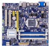
- Foxconn Q77M | User manual - Page 1
Q77M/B75M Series Motherboard User's Manual - Foxconn Q77M | User manual - Page 2
property of their respective owners. Version: User's Manual V1.1 for Q77M/B75M motherboard. Symbol description: Note: refers to important information that can help you to use motherboard better, and tells you how to avoid problems. Caution: indicating a potential risk of hardware damage - Foxconn Q77M | User manual - Page 3
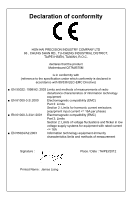
HON HAI PRECISION INDUSTRY COMPANY LTD 66 , CHUNG SHAN RD., TU-CHENG INDUSTRIAL DISTRICT, TAIPEI HSIEN, TAIWAN, R.O.C. declares that the product Motherboard Q77M/B75M is in conformity with (reference to the specification under which conformity is declared in accordance with 89/336 EEC-EMC Directive - Foxconn Q77M | User manual - Page 4
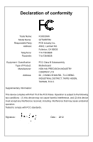
Party: Address: Telephone: Facsimile: FOXCONN Q77M/B75M PCE Industry Inc. 458 E. Lambert Rd. Fullerton, CA 92835 714-738-8868 714-738-8838 Equipment Classification: Type of Product: Manufacturer: Address: FCC Class B Subassembly Motherboard HON HAI PRECISION INDUSTRY COMPANY LTD - Foxconn Q77M | User manual - Page 5
placed on the motherboard or within the computer casing. ■ If you are uncertain about any installation steps or have a problem related to the use of the product, please consult a certified computer technician. Technical Support Website: http://www.foxconnchannel.com Support Website: http://www - Foxconn Q77M | User manual - Page 6
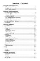
other Internal Connectors 14 2-5 Jumpers 18 Chapter 3 BIOS Setup Enter BIOS Setup 21 Main...22 F-center...24 Smart BIOS 24 Fox Intelligent Stepping 25 CPU Configuration 26 Save & Exit 42 Chapter 4 CD Instruction 4-1 Install driver and utility 44 1. Driver 44 2. Utility...45 4-2 FOX ONE 46 - Foxconn Q77M | User manual - Page 7
68 Intel® Rapid Storage Technology enterprise 70 Steps to Install Serial ATA Hard Disks 70 5-1 Create a RAID driver diskette 71 5-2 BIOS Configuration 72 5-3 Create RAID in BIOS 72 Enter RAID BIOS Setup 72 Create RAID Volume 73 Delete RAID Volume 88 Reset Disks to Non-RAID 89 Recovery - Foxconn Q77M | User manual - Page 8
Chapter 1 Product Introduction Thank you for buying Foxconn Q77M/B75M Series motherboard. Foxconn products are engineered to maximize computing power, providing only what you need for break-through performance. This chapter includes the following information: ■ Product Specifications ■ Layout ■ - Foxconn Q77M | User manual - Page 9
(6Gb/s data transfer rate) Q77M: - Intel 82579LM Lan chip - Support Intel vPro Technology - Support 10/100/1000Mbps B75M: - Realtek RTL8111F Lan chip - Support 10/100/1000Mbps Realtek ALC662 Audio chip: - High Definition Audio - 2/4/5.1-channel - Support Jack-Sensing function - Support up to 8 x USB - Foxconn Q77M | User manual - Page 10
(Q77M) 5 x SATA 2.0 + 1 x SATA 3.0 connectors (B75M) 3 x USB 2.0 headers (supporting 6 x USB devices) 1 x USB 3.0 header (supporting 2 Display port 2 x USB 2.0 ports 2 x USB 3.0 ports 3 x Audio ports System voltage detection CPU/System temperature detection CPU/System fan speed detection CPU - Foxconn Q77M | User manual - Page 11
4. PCI Express X16 Slot PCI Express X1 Slot 5. PCI Slots 6. CD_IN Header 7. Front Audio Header 8. SPDIF_OUT Header 9. ME Header 10. Front USB Header 11.Clear CMOS Header 12. Front Header 25. SYS_FAN2 Header Note : The above motherboard layout is for reference only, please refer to the physical - Foxconn Q77M | User manual - Page 12
Port 4 DVI-D Port 6 7 8 10 Display Ports USB 3.0 Ports USB 2.0 Ports Audio Ports 1. PS/2 Mouse Port Use the upper port (green) to connect a PS/2 need to install the USB 3.0 driver in the Driver CD before using it. 8. USB 2.0 Ports The USB port supports the USB 2.0/1.1 specification. Use this - Foxconn Q77M | User manual - Page 13
Out* Front Speaker Out Microphone In 5.1-channel Rear Speaker Out* Front Speaker Out Center/Subwoofer Out* *: Please refer to Chapter 4, and run the Realtek audio driver (in CD) to assign the audio output ports for different applications of 2/4/5.1 channels or 2/4/5/7.1 channels. The fundamental - Foxconn Q77M | User manual - Page 14
slots, pin headers and the mounting of jumpers. Caution should be exercised during the installation of these modules. Please refer to the motherboard layout prior to any installation and read the contents in this chapter carefully. This chapter includes the following information : ■ Install the CPU - Foxconn Q77M | User manual - Page 15
HT Technology ■ An operating system that is optimized for HT Technology ■ A BIOS that supports HT Technology and has it enabled Install the CPU Locate the alignment keys on the motherboard CPU socket and the notches on the CPU. LGA1155 CPU Socket Alignment Key Pin-1 corner of the CPU Socket - Foxconn Q77M | User manual - Page 16
HARDWARE INSTALLATION Follow the steps to install the CPU onto the CPU socket : Before installing the CPU, make sure to turn off the computer and unplug the power cord from the power outlet to prevent damage to the CPU. 1. Release the CPU socket lever. 2. Lift the metal cover on the CPU socket. - Foxconn Q77M | User manual - Page 17
as depicted in the picture. 3 2 1 4. Attach the 4-wire CPU cooler connector to the CPU FAN header on the motherboard . Release bolts of CPU cooler from motherboard : 1.Turning the push pin (bolt) along with the direction of arrow (counterclockwise). 2. Pull the push pin straight up. 3. Turning - Foxconn Q77M | User manual - Page 18
2-2 Install the Memory HARDWARE INSTALLATION Read the following guidelines before you begin to install the memory : ■ Make sure that the motherboard supports the memory. It is recommended that memory of the same capacity, brand, speed, and chips be used, and please select Dual channel first to - Foxconn Q77M | User manual - Page 19
144-Pin 96-Pin HARDWARE INSTALLATION Installing a Memory If you take a look at front side of memory module, it has asymmetric pin counts on both sides separated by a notch in the middle, so it can only fit in one direction. Follow the steps below to correctly install your memory modules into the - Foxconn Q77M | User manual - Page 20
Expansion Card HARDWARE INSTALLATION ■ Make sure the motherboard supports the expansion card. ■ Always turn off the your computer. If necessary, go to BIOS Setup to make any required BIOS changes for your expansion card(s). 7. Install the driver provided with the expansion card in your operating - Foxconn Q77M | User manual - Page 21
PWR1 is the ATX power supply connector. Make sure that the power supply cable and pins are properly aligned with the connector on the motherboard. Firmly plug the power supply cable into the connector and make sure it is secure. Pin # Definition Pin # Definition 1 3.3V 13 3.3V 2 3.3V 14 - Foxconn Q77M | User manual - Page 22
4 SPDIF_OUT Audio Header : F_AUDIO The audio connector supports HD Audio standard. It provides the Front Audio output choice. on the rear panel, this product also provides 10-pin USB headers on its motherboard. By connecting through USB cables with them, user can quickly expand another USB ports - Foxconn Q77M | User manual - Page 23
HARDWARE INSTALLATION Front Panel Header : FP1 This motherboard includes one connector for connecting the front panel this motheboard. The fan speed can be controlled and monitored in " Health" section of the BIOS Setup. These fans can be automatically turned off after the system enters S3, S4 and S5 - Foxconn Q77M | User manual - Page 24
the external RS232 device and another end with 10-pin female connector to connect with COM1 connector in the motherboard. LPT Hearder (optional) : LPT The connector supports parallel port which can be connected to a printer or a scanner. System usually assign IRQ7 as it's default interrupt request - Foxconn Q77M | User manual - Page 25
motherboard, pin 1 can be identified by the bold silkscreen next to it. However, in this manual It can prevent hazardous ESD (Electrical Static Discharge) problem. Jumper 1 1 Diagram 1 1 1 1 : CLR_CMOS The motherboard uses CMOS RAM to store the basic hardware information (such as BIOS data, date, - Foxconn Q77M | User manual - Page 26
HARDWARE INSTALLATION Intel® ME Jumper: PCH_ME_ENABLE This motherboard uses MFG jumper to enable or disable Intel® Management Engine closed Set Pin 2 and Pin 3 closed Function Enable ME function Disable ME function CAUTION Before flashing BIOS ROM, you need to set ME jumper to pins 2-3 first. 19 - Foxconn Q77M | User manual - Page 27
Setup This chapter tells how to change system settings through the BIOS Setup menus. Detailed descriptions of the BIOS parameters are also provided. You have to run the Setup Program when the following cases occur: 1. An error message appears on the screen during the - Foxconn Q77M | User manual - Page 28
ways (such as less I/O cards, less memory ...etc.), still, it may cause problem if you have more memory or I/O cards installed. It means, if your system loading sometimes come out an unstable system. What you need now is to adjust BIOS setting one by one, trial and error, to find out the best setting - Foxconn Q77M | User manual - Page 29
Memory MAC Address [Sun 01/01/2012] [16:02:30] Administrator Q77M 8.1.0.1265 BA2F1B04 10/17/2012 21:00:32 [All, but keyboard B75M Motherboard --Model Name:B75M ► System Date format. Day-weekday from Sun. to Sat., this message is automatically displayed by BIOS - Foxconn Q77M | User manual - Page 30
BIOS SETUP [All Errors]: All errors can result in system halt. [No Errors]: No error can result in system halt. [All, but keyboard]: All errors but - Foxconn Q77M | User manual - Page 31
ESC/Right Click: Exit Version 2.14.1219. Copyright (C) 2012 American Megatrends, Inc. ► Super BIOS Protect To protect the system BIOS, there is a BIOS write-protection mechanism provided to prevent BIOS FLASH tool being improperly used to update BIOS or the vicious virus(such as CHI,etc) rewriting - Foxconn Q77M | User manual - Page 32
BIOS SETUP ► Smart Power LED Smart Power LED is a feature built on your motherboard to indicate different states during Power On Self Test (POST). The LED is located at the front panel, and it displays POST state by different - Foxconn Q77M | User manual - Page 33
Intel VT-x Technology Intel SMX Technology Intel AES-NI Intel XD Bit Limit CPUID Maximum Intel Virtualization Technology CPU C3 Report CPU C6 Report Power Health 32 KB X 4 32 KB X 4 256 KB X 4 8192 KB 4 2200 MHZ 1600 MHz 2200 MHz 4 Not Supported Supported Supported [Enabled - Foxconn Q77M | User manual - Page 34
chipset, motherboard, BIOS and operation system. Please refer to Intel Website for more information. ► Turbo Mode(Appears only when CPU supports) timing profile 1. The following items appear only when the option is set to "Manual". ► Memory Clock Multiplier This item is used to set the memory clock - Foxconn Q77M | User manual - Page 35
the read CAS_L isasserted depends on the memory clock frequency. The value that BIOS programs into the memory controller is a function of the target clock frequency. The target clock frequency is determined from the supported CAS latencies at given clock frequencies of each DIMM. ► tRP This item - Foxconn Q77M | User manual - Page 36
Advanced BIOS SETUP Main F-center Advanced Boot ▶ Note: AMT Configuration item is unavailable on B75M Motherboard . ► North Bridge/ME Subsystem/AMT Configuration Configuration Integrated Graphics UMA Frame buffer Size Initate Graphics Adapter VT-d IGD Multi-Montior DVMT/FIXED Memory 2048 MB ( - Foxconn Q77M | User manual - Page 37
BIOS SETUP ► Memory Slot 1/2/3/4 These items display the memory size installed on each slot. ► Integrated Graphics This item allows you to determine whether to allocate memory for the integrated graphics controller from the system memory. Options: [Auto], [Manual during driver initialization. - Foxconn Q77M | User manual - Page 38
Intel vPro function. Onboard Device Configuration BIOS SETUP Main F-center Advanced Boot Power Health Security Save&Exit OOnnbbooaarrdd LDAeNviCcoentCroonlfliegruration Onboard LAN Controller Onboard LAN PXE OpROM Onboard USB Controller Legacy USB Support USB3.0 Support Azalia HD Audio - Foxconn Q77M | User manual - Page 39
BIOS Megatrends, Inc. Note: SATA Mode subitem RAID is unavailable on B75M Motherboard. ► SATA Controller(s) This item is used to enable or support AHCI, unless they are labeled with AHCI support in its specification. If your motherboard supporting AHCI, and you have a SATA device, which also supports - Foxconn Q77M | User manual - Page 40
Super IO Configuration BIOS SETUP Main F-center Advanced Boot Power Health Security Save&Exit Super IO Configuration Super IO Chip IT8728 Set Parameters of Serial Port 0 (COMA) ▶ Serial Port 0 - Foxconn Q77M | User manual - Page 41
NO TPM Hardware Power Health [Disabled] Security Save&Exit Enables or Disables BIOS support O.S. will not show TPM.Reset of platform is required. → ←: option is [Disabled]. If you want to support TPM, first you need to install a TPM device on the motherboard and set this item to [Enabled], - Foxconn Q77M | User manual - Page 42
Network Stack BIOS SETUP Main F-center Advanced Boot Power Health Security Save&Exit Network stack [Disabled] Enable/Disables UEFI network stack → ←: Select Screen ↑ ↓/Click: Select Item Enter/Dbl - Foxconn Q77M | User manual - Page 43
. [Disabled] : Displays the normal POST messages. [Enabled] : Displays OEM customer logo instead of POST messages. ► Fast Boot While Enabled, this option allows BIOS to skip certain tests while booting, this will shorten thetime needed to boot the system. ► Interrupt 19 Capture Enable this item can - Foxconn Q77M | User manual - Page 44
CSM parameters BIOS SETUP Main F-center Advanced Boot Power Health Security Save&Exit Launch CSM Boot option filter Launch PXE OpROM policy Launch Storage OpROM policy Launch Video - Foxconn Q77M | User manual - Page 45
- The S4 sleeping state is the lowest power, longest wake latency sleeping state supported by ACPI. In order to reduce power to a minimum, it is assumed S5 state and the S4 state to allow for initial boot operations within the BIOS to distinguish whether or not the boot is going to wake from a saved - Foxconn Q77M | User manual - Page 46
BIOS SETUP return to previous state when the STR function wakes. ► Resume suspend power of the chipset will be cut off in S5 suspend mode in order to reduce the power consumption of motherboard. Enabled: S1/S3/S4 is normal, S5 wake up only by pressing the power button. Disabled: Normal ACPI function - Foxconn Q77M | User manual - Page 47
Instruction Alarm will appear. If don't enter bios setup and disabled Case Opening Warning one time, Instruction CPU is higher than the set value, the motherboard will send out warning information. ► CPU function works only when your operating system is supporting ACPI. ► CPU Smart Fan Control This - Foxconn Q77M | User manual - Page 48
Security BIOS SETUP Main F-center Advanced Boot Power Health Security Save&Exit Security configuration Administrator Password User Password Administator Password HDD BootSector Write ▶ Secure Boot menu Not - Foxconn Q77M | User manual - Page 49
Defaults Optimal defaults are the best settings of this motherboard. Always load the Optimal defaults after updating the BIOS or after clearing the CMOS values. Select this the optimal performance parameters to be set cannot be supported by your hardware devices (for example, too many expansion - Foxconn Q77M | User manual - Page 50
Chapter 4 CD Instruction The utility CD that comes with the motherboard contains useful software and several utility drivers that enhance the motherboard features. This chapter includes the following information: ■ Install driver and utility ■ FOX ONE ■ FOX LiveUpdate ■ FOX LOGO ■ FOX DMI ■ Smart - Foxconn Q77M | User manual - Page 51
, or you can click on each individual driver to install it manually. Manual Installation Step by Step Automatic Installation by One Click Drop to System Tray Exit the program Visit Foxconn's Show Utilities Show Drivers Browse CD View the Utility Website Help files Choose the items you want to - Foxconn Q77M | User manual - Page 52
CD INSTRUCTION 2. Utility Use these options to install additional software programs. And click "User's manual" button to view the product manual. Click here The Driver and Utility items displayed above represent a Windows 7 based system. The appearance may change with different Operating Systems. 45 - Foxconn Q77M | User manual - Page 53
INSTRUCTION performance options. ■ Monitor hardware temperatures, voltages, frequencies and fan speeds. Supporting Operating Systems : ■ Windows 8 (32-bit and 64-bit) ■ system parameters (such as CPU clock, voltage...etc.) are controlled by BIOS settings. After you run FOX ONE, it will take over, and - Foxconn Q77M | User manual - Page 54
1. Main Page Show CPU Information Toolbar CD INSTRUCTION Alert Lamp Switch Button Skin Button Exit Minimum Configuration Homepage Monitor Frequency/Voltage/Fan speed/Temperature value Toolbar Use the toolbar to navigate to other - Foxconn Q77M | User manual - Page 55
CD INSTRUCTION Click the new skin picture to select the new skin Apply the changes tray located at the lower right corner of your screen. Homepage Click this button to visit Foxconn motherboard website : http://www.foxconnchannel.com Configuration 1). Monitor interval (ms) : This is to define the - Foxconn Q77M | User manual - Page 56
CD INSTRUCTION 2). Simple Mode : To select which message of system settings are to be displayed in the Simple Mode. Messages such as CPU frequency, voltage...etc., they - Foxconn Q77M | User manual - Page 57
CD INSTRUCTION 2. CPU Page - CPU Control This page lets you select (or overclock) CPU clock to meet the current performance level of the system. The fastest and suitable CPU clock running for current system can be calculated by FOX ONE automatically or manually input by yourselves. Manual : You can - Foxconn Q77M | User manual - Page 58
CD INSTRUCTION A message informs you to push RESET button later if the system hangs finally. Click Yes to continue. You can see the system is raising CPU - Foxconn Q77M | User manual - Page 59
CD INSTRUCTION Now, your system is running at a CPU clock of 255MHz. FOX Intelligent Stepping (F.I.S., Optional) Select FOX Intelligent Stepping will allow your system to automatically adjust - Foxconn Q77M | User manual - Page 60
Frequency Control(Optional) This page lets you set memory and PCI Express frequencies by manual. CD INSTRUCTION Go to Freq. page Close this page Select the option you want to set Adjust by manual Reset the changes Apply the changes 4. Limit Setting 4.1 Limit Setting - CPU Temperature This page - Foxconn Q77M | User manual - Page 61
CD INSTRUCTION 4.2 Limit Setting - System Temperature This page lets you to set system high limit temperature and enable the alert function. Show current system temperature value Enable - Foxconn Q77M | User manual - Page 62
CD INSTRUCTION 4.4 Limit Setting - System Fan This page lets you to set system fan low limit rpm and enable the alert function. Show current system fan rpm - Foxconn Q77M | User manual - Page 63
CD INSTRUCTION 5. Voltage Page - Voltage Control (Optional) This page lets you set CPU voltage, memory voltage and North Bridge voltage manually. CPU voltage Go to Voltage page Select the option you want to set Adjust by manual Reset the changes Apply the changes 6. Fan Page - Fan Control This page - Foxconn Q77M | User manual - Page 64
CD INSTRUCTION FOX LiveUpdate is a useful utility to backup and update your system BIOS, drivers and utilities by local or online. Supporting Operating Systems : ■ Windows 8 (32-bit and 64-bit) ■ Windows 7 (32-bit and 64-bit) ■ Windows XP (32-bit and 64-bit) Please set the BIOS setting "BIOS - Foxconn Q77M | User manual - Page 65
INSTRUCTION Key in a BIOS name Click here 1-3 Local Update - Update This page helps you to update your BIOS from a local file. After click "Update", An alert message will be displayed to ensure if you really want to continue, click "Yes" to confirm. A setup wizard will guide you to load a local BIOS - Foxconn Q77M | User manual - Page 66
the update operation. Click here Current information Select BIOS to update Search new BIOS from Internet Browse detailed information Update BIOS Close the window 2-2 Online Update - Update Driver This page lets you update your system drivers from Internet. Click "Start", it will search the - Foxconn Q77M | User manual - Page 67
CD INSTRUCTION Select the driver to update Browse detailed information Install the selected driver Close the window 2-3 Online Update - Update Utility This page lets you update utilities from Internet. Click "Start", it will search the new utilities from Internet. - Foxconn Q77M | User manual - Page 68
CD INSTRUCTION 2-4 Online Update - Update All This page lets you update your system drivers from Internet. Click "Start", it will search all new BIOS/drivers/utilities from Internet. Then follow the wizard to finish the update operation. Click here Current information Search all new BIOS/ drivers/ - Foxconn Q77M | User manual - Page 69
CD INSTRUCTION 3. Configure 3-1 Configure - option This page lets you set auto search options. After you enable the auto search function, FOX LiveUpdate will start its searching from - Foxconn Q77M | User manual - Page 70
CD INSTRUCTION When you enable "Auto Search FOX LiveUpdate", if your FOX LiveUpdate version is older, it will auto search from internet and prompt you to install the new version. Prompt you to install the new FOX LiveUpdate 3-2 Configure - System This page lets you set the backup BIOS location and - Foxconn Q77M | User manual - Page 71
protective, and you must make sure the flash process is continuous and without any interruption. Click here Select which BIOS ROM to flash(Only available to motherboard with backup BIOS ROM ) Select to flash Boot Block Apply the changes Reset to default value We recommend that you had better keep - Foxconn Q77M | User manual - Page 72
INSTRUCTION the "Quiet Boot" setting in BIOS. Supporting Operating Systems : ■ Windows 8 ( Website About CAUTION When you change Logo or delete current Logo, the system will flash BIOS file automatically. During this time, please DO NOT shut down the application and the system, or the motherboard - Foxconn Q77M | User manual - Page 73
CD INSTRUCTION 4-5 FOX DMI FOX DMI is a full Desktop Management Interface viewer, and it provides three DMI data formats: Report, Data Fields and Memory Dump. With DMI information, system maker can easily analyze and troubleshoot your motherboard if there is any problem occurred. Supporting - Foxconn Q77M | User manual - Page 74
: ■ Installing a new Windows XP (Windows 7) in a brand new RAID system. It includes the following information : ■ RAID Configuration Introduction ■ Intel® Rapid Storage Technology enterprise ■ Create a RAID Driver Diskette ■ BIOS Configuration ■ Create RAID in BIOS ■ Install a New Windows XP - Foxconn Q77M | User manual - Page 75
BIOS. 4. Follow 5-4 to Install Windows Operating System. What kinds of hardware and software you need here : 1. A floppy drive. 2. A CD-ROM drive. 3. Several SATA hard disks. 4. A RAID driver diskette. 5. A motherboard driver performance in different ways. The problem with using more disks is that - Foxconn Q77M | User manual - Page 76
number of drive members times the capacity of the smallest member. The striping block size can be set from 4KB to 128KB. RAID 0 does not support fault tolerance. RAID 1 (Mirror) RAID 1 writes duplicate data onto a pair of drives and reads both sets of data in parallel. If one of the mirrored - Foxconn Q77M | User manual - Page 77
enterprise technology supports RAID 0 SATA hard disks as an example to guide you how to configure your RAID Connect one end of the SATA cable to motherboard's SATA connector, and the other end to driver. ■ Set SATA mode in BIOS to AHCI, you can skip RAID BIOS creation steps, but the software driver - Foxconn Q77M | User manual - Page 78
on a AHCI or RAID system, you need to configure the SATA Mode in BIOS to either AHCI or RAID first. You also need to create a RAID driver diskette for use in installing your Windows XP system. Windows 7 has native RAID driver in itself, you can skip these steps. 1. Find a PC, put a diskette into - Foxconn Q77M | User manual - Page 79
system, it will ask you to use this floppy diskette to provide driver for additional specific devices, for example, a RAID device. 10. Install into the drive bays, connect all power and SATA cables. 5-2 BIOS Configuration 1. Enter the BIOS setup by pressing key during the POST(Power On Self - Foxconn Q77M | User manual - Page 80
RAID CONFIGURATION Create RAID Volume Create RAID 0 (1st Volume) 1. Select "1. Create RAID Volume" from the menu and press . The menu appears : Intel(RIn)teMl(aRt)rixRaSptoidraSgteorMagaenaTgeecrhnoopltoiognyR-OUMpvti5o.n0.R0O.1M01-11I1C.H0.98R.12w0R4AID5 Copyright(C) 2003-1014 IInntteell - Foxconn Q77M | User manual - Page 81
RAID CONFIGURATION Intel(RIn)teMl(aRtr)ixRSaptoidraSgteorMagaenaTgeecrhonpotlioognyR-OUMpvti5o.n0.R0.O1M011- 1IC1.H0.98R.1w20R4AID5 CCooppyyrriigghhtt((CC)) 22000033--1014 IInntteell CCoorrppoorraattiioonn. AAll lRl RigihgthstsRReseesrevrevde.d. [ CREATE VOLUME MENU ] Name: TryRAID0 RAID - Foxconn Q77M | User manual - Page 82
RAID CONFIGURATION Intel(RIn)teMl(aRtr)ixRSaptoidraSgteorMaagneaTgeecrhonpotlioognyR-OUMpvti5o.n0.R0.O1M011- 1IC1.H0.98R.1w20R4AID5 Copyright(C) 2003-1014 IInntteell CCoorrppoorraattiioonn. AlAl lRl RigihgthstsRReseesrevrevde.d. [ CREATE VOLUME MENU ] Name: TryRAID0 RAID Level: RAID0(Stripe - Foxconn Q77M | User manual - Page 83
RAID CONFIGURATION Intel(RIn)teMl(aRtr)ixRSaptoidraSgteorMaagneaTgeecrhonpotlioognyR-OUMpvti5o.n0.R0.O1M011- 1IC1.H0.98R.1w20R4AID5 Copyright(C) 2003-1014 IInntteell CCoorrppoorraattiioonn.AlAl lRl RigihgthstsRReseesrevrevde.d. [ CREATE VOLUME MENU ] Name: TryRAID0 RAID Level: RAID0(Stripe) - Foxconn Q77M | User manual - Page 84
RAID CONFIGURATION Create RAID0 (2nd Volume) 1. Select "1. Create RAID Volume" from the menu and press . The menu appears : Intel(RIn)teMl(aRtr)ixRSaptoidraSgteorMaagneaTgeecrhonpotlioognyR-OMUpvti5o.n0.R0.O10M11- 1IC1.H09.8R.1w20R4AID5 Copyright(C) 2003-1014 IInntteell - Foxconn Q77M | User manual - Page 85
RAID CONFIGURATION Intel(IRn)teMl(aRt)riRx aSptoidraSgteorMagaenaTgeecrhnoopltoiogny R-OUMpvti5o.n0.R0O.1M01-11I1C.0H.98R.12w0R4AID5 CCooppyyrriigghhtt((CC)) 22000033--1014 IInntteell CCoorrppoorraattiioonn. AAll lRl RigihgthstsRReseesrevrevde.d. [ CREATE VOLUME MENU ] Name: TryRAID0-1 RAID - Foxconn Q77M | User manual - Page 86
RAID CONFIGURATION Intel(RIn)teMl(aRtr)ixRSaptoidraSgteorMaagneaTgeecrhonpotlioognyR-OUMpvti5o.n0.R0.O1M011- 1IC1.H0.98R.1w20R4AID5 Copyright(C) 2003-1014 IInntteell CCoorrppoorraattiioonn. AlAl lRl RigihgthstsRReseesrevrevde.d. [ CREATE VOLUME MENU ] Name: TryRAID0-1 RAID Level: RAID0( - Foxconn Q77M | User manual - Page 87
RAID CONFIGURATION Create RAID 1 1. Select "1.Create RAID Volume" from the main menu and press . 2. In "Name" item, you can input a device name for the RAID1 system and press to apply it. Here, we name it as TryRAID1 to replace the default Volume0. Intel(RIn)teMl(aRt) - Foxconn Q77M | User manual - Page 88
RAID CONFIGURATION 4. It then goes to "Disks" item. Press to dispaly the hard disks list for this RAID1 system. Intel(RIn)teMl(aRtr)ixRSaptoidraSgteorMagaenaTgeecrhonpotlioognyR-OUMpvti5o.n0.R0.O1M011- 1IC1.H0.98R.1w20R4AID5 CCooppyyrriigghhtt((CC)) 22000033--1014 IInntteell - Foxconn Q77M | User manual - Page 89
RAID CONFIGURATION 6. It will skip "Strip Size" menu for RAID1. Intel(RIn)teMl(aRtr)ixRSaptoidraSgteorMaagneaTgeecrhonpotlioognyR-OUMpvti5o.n0.R0.O1M011- 1IC1.H0.98R.1w20R4AID5 Copyright(C) 2003-1014 IInntteell CCoorrppoorraattiioonn. AlAl lRl RigihgthstsRReseesrevrevde.d. [ CREATE VOLUME MENU ] - Foxconn Q77M | User manual - Page 90
Create RAID 10 (0+1) RAID CONFIGURATION 1. Select "1.Create RAID Volume" from the main menu and press . 2. In "Name" item, you can input a device name for the RAID10 system and press to apply it. Here, we name it as TryRAID10 to replace the default Volume0. Intel(RIn)teMl(aRt) - Foxconn Q77M | User manual - Page 91
RAID CONFIGURATION 5. Use Up or Down arrow key to select the desired strip size when entering "Strip Size" menu. The default value is 64K. Intel(RIn)teMl(aRtr)ixRSaptoidraSgteorMaagneaTgeecrhonpotlioognyR-OUMpvti5o.n0.R0.O1M011- 1IC1.H0.98R.1w20R4AID5 Copyright(C) 2003-1014 IInntteell - Foxconn Q77M | User manual - Page 92
Create RAID5 (Parity) RAID CONFIGURATION 1. Select "1.Create RAID Volume" from the main menu and press . 2. In "Name" item, you can input a device name for the RAID5 system and press to apply it. Here, we name it as TryRAID5 to replace the default Volume0. Intel(RIn)teMl(aRt) - Foxconn Q77M | User manual - Page 93
RAID CONFIGURATION 4. It then goes to "Disks" item. Press to display the hard disks list for this RAID5 system. Intel(RIn)teMl(aRtr)ixRSaptoidraSgteorMagaenaTgeecrhonpotlioognyR-OUMpvti5o.n0.R0.O1M011- 1IC1.H0.98R.1w20R4AID5 CCooppyyrriigghhtt((CC)) 22000033--1014 IInntteell - Foxconn Q77M | User manual - Page 94
RAID CONFIGURATION 6. Use Up or Down arrow key to select the desired strip size when entering "Strip Size" menu. The default value is 64K. Press . Intel(IRn)teMl(aRt)riRx aSptoidraSgteorMagaenaTgeecrhnoopltoiognyR-OUMpvti5o.n0.R0O.1M01-11I1C.H0.98R.12w0R4AID5 Copyright(C) 2003-1014 - Foxconn Q77M | User manual - Page 95
RAID CONFIGURATION Delete RAID Volume 1. Take TryRAID5 for example. Select "2. Delete RAID Volume" in main menu and press . Intel(IRn)teMl(aRt)riRx aSptoidraSgteorMagaenaTgeecrhnoopltoiognyR-OUMpvti5o.n0.R0O.1M01-11I1C.H0.98R.12w0R4AID5 Copyright(C) 2003-1014 IInntteell - Foxconn Q77M | User manual - Page 96
RAID CONFIGURATION Intel(RIn)teMl(aRt)rixRaSptoidraSgteorMagaenaTgeecrhnoopltoiognyR-OUMpvti5o.n0.R0O.1M01-11I1C.H0.98R.12w0R4AID5 Copyright(C) 2003-1014 IInntteell CCoorrppoorraattiioonn.AlAl lRl RigihgthstsRReseesrevrevde.d. [ DELETE VOLUME MENU ] Name TryRAID05 Level Drives RIDA0I(DS5tr - Foxconn Q77M | User manual - Page 97
RAID CONFIGURATION Example 1. Reset a RAID0 system. 1. A TryRAID0 volume was built with two 149.0GB hard disks, we want to reset one of them. Select "3. Reset Disks to Non-RAID" in main menu and press . Intel(IRn)teMl(aRt)riRx aSptoidraSgteorMagaenaTgeecrhnoopltoiognyR-OUMpvti5o.n0.R0O. - Foxconn Q77M | User manual - Page 98
RAID CONFIGURATION 3. Select Hitachi hard disk as the one to be reset. Press . A double confirmation message pops out, press to confirm. Intel(IRn)teMl(aRt)riRx aSptoidraSgteorMagaenaTgeecrhnoopltoiognyR-OUMpvti5o.n0.R0O.1M01-11I1C.H0.98R.12w0R4AID5 Copyright(C) 2003-1014 IInntteell - Foxconn Q77M | User manual - Page 99
RAID CONFIGURATION Example 2. Reset a RAID5 system 1. A TryRAID5 volume was built with three hard disks, we want to reset one of them. Select "3. Reset Disks to Non-RAID" in main menu and press . Intel(RIn)teMl(aRtr)ixRSaptoidraSgteorMaagneaTgeecrhonpotlioognyR-OUMpvti5o.n0.R0.O1M011- 1IC1. - Foxconn Q77M | User manual - Page 100
RAID CONFIGURATION Intel(IRn)teMl(aRt)riRx aSptoidraSgteorMagaenaTgeecrhnoopltoiognyR-OUMpvti5o.n0.R0O.1M01-11I1C.H0.98R.12w0R4AID5 Copyright(C) 2003-1014 IInntteell CCoorrppoorraattiioonn. AlAl lRl RigihgthstsRReseesrevrevde.d. [ MAIN MENU ] 1. Create RAID Vo[luDmEeG RA DED VOLUME DET4E. - Foxconn Q77M | User manual - Page 101
RAID CONFIGURATION Recovery Volume Options 1. "Recovery Volume Options" is only available when "Recovery" is built. Here, we take TryRecovery as an example, select "4. Recovery Volume Options" in main menu and press . The screen displays: Intel(RIn)teMl(aRtr) - Foxconn Q77M | User manual - Page 102
5GB Non-RAID Disk [↑↓]-Select [ESC]-Exit [ENTER]-Select Menu 2. Press to exit Intel® Rapid Storage Technology enterprise program. The system will enter BIOS setup. 3. Shut down the computer, remove the Non-RAID disk, and we will continue for Windows OS installation. If you do not - Foxconn Q77M | User manual - Page 103
optical drive. 3. Set the first Boot device to CD/DVD, save changes and exit the BIOS setup. (Please refer to Chapter 3 BIOS Setup) 4. The computer will reboot, and it will start installing Windows Operating System. Watch Setup Press F6 if you need to install a third party SCSI or RAID driver. 96 - Foxconn Q77M | User manual - Page 104
storage devices installed in your system, or you have chosen to manually specify an adapter. Currently, Setup will load support for the following mass storage device(s): * To specify additional SCSI adapters, CD-ROM drivers, or special disk controllers for use with Windows, including those - Foxconn Q77M | User manual - Page 105
to select it. If the SATA mode in BIOS is set to AHCI, this screen will show different drivers, and we need choose "Intel(R) Desktop/Workstation/ to double check if the driver is really what we wanted. Press to continue. Windows Setup Setup will load support for the following mass storage - Foxconn Q77M | User manual - Page 106
remember. 11. Follow the Windows XP install processes to finish the set up. Windows XP Professional Setup Insert the disk labeled: Intel Matrix Storage Manager driver into drive A: * Press ENTER when ready F3=Quit ENTER=Continue 99
-
 1
1 -
 2
2 -
 3
3 -
 4
4 -
 5
5 -
 6
6 -
 7
7 -
8
-
9
-
10
-
11
-
12
-
13
-
14
-
15
-
16
-
17
-
18
-
19
-
20
-
21
-
22
-
23
-
24
-
25
-
26
-
27
-
28
-
29
-
30
-
31
-
32
-
33
-
34
-
35
-
36
-
37
-
38
-
39
-
40
-
41
-
42
-
43
-
44
-
45
-
46
-
47
-
48
-
49
-
50
-
51
-
52
-
53
-
54
-
55
-
56
-
57
-
58
-
59
-
60
-
61
-
62
-
63
-
64
-
65
-
66
-
67
-
68
-
69
-
70
-
71
-
72
-
73
-
74
-
75
-
76
-
77
-
78
-
79
-
80
-
81
-
82
-
83
-
84
-
85
-
86
-
87
-
88
-
89
-
90
-
91
-
92
-
93
-
94
-
95
-
96
-
97
-
98
-
99
-
100
-
101
-
102
-
103
-
104
-
105
-
106
 |
 |

Q77M/B75M Series
Motherboard
User’s Manual