Frigidaire FAFS4473LW Wiring Diagram (All Languages)
Frigidaire FAFS4473LW Manual
 |
UPC - 012505382246
View all Frigidaire FAFS4473LW manuals
Add to My Manuals
Save this manual to your list of manuals |
Frigidaire FAFS4473LW manual content summary:
- Frigidaire FAFS4473LW | Wiring Diagram (All Languages) - Page 1
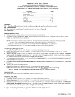
Washer Tech Data Sheet This information is intended for Qualified Technicians Only. CAUTION: DISCONNECT ELECTRICAL CURRENT BEFORE SERVICING experienced. Troubleshoot the problem by using charts on the pages 3-5. If there is no error displayed and the washer momentarily models. 1 137309200A (1003) - Frigidaire FAFS4473LW | Wiring Diagram (All Languages) - Page 2
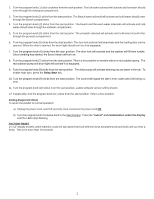
(6) clicks from the start position. The door lock will activate and the washer will fill then tumble. Once tumbling has started, the Boost Heater will display until the LEDs stop flashing. FACTORY RESET 1¼"x2" display models, wake machine, push the spin speed and soil selection keys simultaneously - Frigidaire FAFS4473LW | Wiring Diagram (All Languages) - Page 3
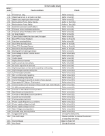
on motor phase. No tacho signal for 3 seconds. High temperature on heat sink caused by overloading. High Voltage experienced by MC. Communication problem. MC is continuously resetting. Heater sensing relay failure. Current leakage to ground on heater or fuse opened. Drum water NTC failure. (Tub - Frigidaire FAFS4473LW | Wiring Diagram (All Languages) - Page 4
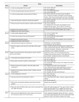
board. Test 5 1. Is the water level above 4.5 inches? 2. Does water enter the washer continuously? 3. Remove power from washer. Does the water stop coming in? 4. Replace the pressure sensor switch. Did this correct the problem? Test 6 1. Is the loading door closed? 2. Can you hear the lock attempt - Frigidaire FAFS4473LW | Wiring Diagram (All Languages) - Page 5
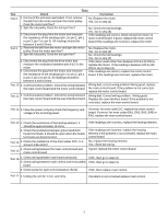
control board and If the readings are incorrect, replace the heating element. If the readings are incorrect, replace the heating element.If the problem is not corrected, replace the main control board. No, replace the heating element. Yes, check the wiring. If good, replace the motor control - Frigidaire FAFS4473LW | Wiring Diagram (All Languages) - Page 6
commande se ferme peu de temps après avoir appuyé sur la touche "Start (Départ)/Pause". 2. Vérifiez si les connexions de la MB sont ajustées fermement. Pour vers la droite de 2 tours (clics) pour revenir à la position de départ (les voyants à DEL clignoteront). Appuyez sur CANCEL (Annuler) et sur le - Frigidaire FAFS4473LW | Wiring Diagram (All Languages) - Page 7
bouton de programmation de cinq (5) positions (clics) à partir de la position de départ. Le solénoïde du verrou de la porte se désactivera et la porte le bouton de programmation de dix (10) positions à partir de la position de départ. La dernière version du logiciel sera présentée. 12. Le cas échéant - Frigidaire FAFS4473LW | Wiring Diagram (All Languages) - Page 8
Tableau des codes d'erreur Code d'erreur Anomalie Vérification E11 Durée de remplissage trop longue. Se référer au test (1). E13 Fuite d'eau dans la cuve ou fuite d'air dans la cloche d'air. Se référer au test (2). E21 Eau pompée trop lentement. Se référer au test (3). E25 Relais du - Frigidaire FAFS4473LW | Wiring Diagram (All Languages) - Page 9
Test Test 1 Test Vérification Correction 1.Est-ce que le flux d'entrée de l'eau est normal ? Oui. Passez à l'étape (4). 2.Est-ce que les robinets d'arrivée de l'eau sont ouverts? 3.Est-ce que la pression d'arrivée d'eau est supérieure à 20 psi ? Non. Passez à l'étape (2) Non. Ouvrez les - Frigidaire FAFS4473LW | Wiring Diagram (All Languages) - Page 10
Test Test Vérification Correction Test 7 1.Débranchez le raccord du moteur et mesurez la résistance des broches 4 et 5 du moteur. Si la valeur lue se situe entre 105 et 130 Ohms, remplacez la carte de contrôle de moteur.Si le compteur indique d'autres valeurs que 105 et 130 Ohms, remplacez le - Frigidaire FAFS4473LW | Wiring Diagram (All Languages) - Page 11
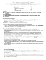
Hoja técnica de lavadora Esta información está destinada exclusivamente a los técnicos calificados. PRECAUCIÓN: DESCONECTE LA CORRIENTE ELÉCTRICA ANTES DE DAR MANTENIMIENTO O SERVICIO Por favor devuelva esta hoja a su sobre en el producto para referencia futura Contenido Página Explicación de los - Frigidaire FAFS4473LW | Wiring Diagram (All Languages) - Page 12
1. Al ingresar al Modo de Diagnóstico, en los modelos con pantallas de 1¼" x 2" todas las luces deben destellar. 2. Gire la perilla de programa (1) click en sentido del reloj desde la posición de inicio. Se activará el solenoide de agua caliente y el agua caliente deberá entrar a través del - Frigidaire FAFS4473LW | Wiring Diagram (All Languages) - Page 13
Código de error Tabla de códigos de error Condición de falla E11 Demasiado tiempo para el llenado. E13 Fuga de agua en la tina o fuga de aire en la campana de aire. E21 El drenado de agua no es lo suficientemente rápido. E25 Sensor de relé de bomba de recirculación E26 Relé de bomba de recirculaci - Frigidaire FAFS4473LW | Wiring Diagram (All Languages) - Page 14
Prueba Prueba 1 Prueba 2 Prueba 3 Prueba 4 Prueba 5 Prueba 6 Prueba Revise Corrección 1.¿El flujo del agua entrante es normal? 2.¿Están abiertas las llaves de agua? 3.La presión del agua entrante está sobre (20) psi. 4.¿El agua para llenado continúa entrando a la lavadora? 5.Quite la corriente - Frigidaire FAFS4473LW | Wiring Diagram (All Languages) - Page 15
Prueba Revise Prueba Corrección Prueba 7 1.Desconecte la clavija del motor de marcha y mida los pines de resistencia números 4 y 5 en el motor. No. Cambie el motor. Si. Vaya al paso (2). Prueba 8 1.Averigüe si la unidad fue sobrecargada. Si no, quite la banda del motor y gire la polea del - Frigidaire FAFS4473LW | Wiring Diagram (All Languages) - Page 16
Tech Data Sheet Part No. 137309200
-
 1
1 -
 2
2 -
 3
3 -
 4
4 -
 5
5 -
 6
6 -
 7
7 -
8
-
9
-
10
-
11
-
12
-
13
-
14
-
15
-
16
 |
 |

137309200A
(1003)
Washer Tech Data Sheet
This information is intended for Qualified Technicians Only.
CAUTION: DISCONNECT ELECTRICAL CURRENT BEFORE SERVICING
Please Return This Sheet to its Envelope in the Product for Future Reference
Contents
Page
Error code explanation
.............................................
1
Diagnostics
........................................................
1-2
Error Code Chart
.....................................................
3
Tests
..................................................................
4-5
Français…………………………………………
.........
6-10
Español…………………………………………
........
11-15
Wiring Diagram……………………………………
........
16
Acronyms:
MB – Main Board (Board located inside machine on right side just behind control panel.)
MC – Motor Control
UI – User interface board (board located inside the front control panel)
DL – Door Lock
READING ERROR CODES
1.
Wake the washer up by pressing any button (except the cancel button).
2.
Press and hold the
“cancel
”
and
“start”
buttons simultaneously for 6 seconds. The failure code will appear in the
display as an E followed by two numbers.
NOTE:
E00 means no failure code experienced.
Troubleshoot the problem by using charts on the pages 3-5.
If there is no error displayed and the washer momentarily starts then turns back off:
1.
Listen for a relay closure inside the control shortly after the
“start/pause”
key is pressed.
2.
Check the connections on the MB make sure that they are firmly snug and secured.
To clear latest stored error code:
•
Press the
“cancel”
button to enter standby mode and enable diagnostic entry.
•
Within 10 seconds after pressing
“cancel”
, press any button (except the cancel button) to wake up the control.
•
Within 5 seconds of wake up, turn the selector knob to the far left cycle and press and hold the
“cancel
”
and
center
button under the display
simultaneously for 3 seconds to enter the Diagnostic Mode.
(note: to save time at wake up,
the welcome screen can be bypassed by turning the selector knob).
•
Turn the program knob clockwise 9 turns (clicks) from the
S
t
art Position. The control will signal the last 5 error codes with
E00 meaning no error experienced.
•
Press and hold the
center key under the display
and
“cancel”
buttons simultaneously for 3 seconds. The code(s) will
be cleared.
•
To return the washer to normal operation.
a) Unplug the power cord, wait 5-8 seconds, then reconnect the power cord
OR
b) Turn the program knob clockwise 2 turns (clicks) back to the
S
t
art Position (LEDs are flashing).
Press the
“cancel
” and
center button under the display
until the LEDs stop flashing.
Diagnostic Test
The diagnostic test is used to check individual component functio
n only.
T
O ST
ART THE TEST
:
•
Press the
“cancel”
button to enter standby mode and enable diagnostic entry.
•
Within 10 seconds after pressing
“cancel”
, press any button (except the cancel button) to wake up the control.
•
Within 5 seconds of wake up, turn the selector knob to the far left cycle and press and hold the
“cancel”
and
the center
button under the display
simultaneously for 3 seconds to enter the Diagnostic Mode.
(note: to save time a
t wake up,
the welcome screen can be bypassed by turning the selector knob).
1.
Upon entering Diagnostic Mode, all lights should flash for 1¼”x2” display models.