Frigidaire FAQE7072LW Wiring Diagram (All Languages) - Page 2
Temperature, Dry Level, Dry Time, DIAGNOSTIC MODE, cancel, cancel, the center, button under - model
 |
UPC - 012505382383
View all Frigidaire FAQE7072LW manuals
Add to My Manuals
Save this manual to your list of manuals |
Page 2 highlights
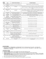
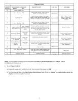
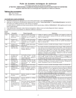
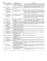
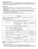
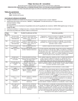
Error Code Fault Possible Fault Conditions Possible Solutions E67 Heaters Sensing Electronic Control Board defective Failure Replace Electronic Control Board and retest. Outlet Control Outlet Control Thermistor or wiring Check resistance of Outlet Control Thermistor, and check wiring for open circuit. E71 Thermistor open defective Resistance should be between 4.9K Ohm and 6.2K Ohm at room temperature circuit (68-77° F or 20-25° C). Replace Outlet Control Thermistor and/or wiring and retest. E72 Outlet Control Thermistor short circuit Outlet Control Thermistor or wiring defective Check resistance of Outlet Control Thermistor, and check wiring for short circuit across Thermistor connections. Resistance should be between 4.9K Ohm and 6.2K Ohm at room temperature (68-77° F or 20-25° C). Replace Outlet Control Thermistor and/or wiring and retest. Communication Wiring, Electronic Control Board, or Check connections between Electronic Control Board and Interface Board. If no E91 Error Interface Board defective wiring problems, replace Electronic Control Board or Interface Board. E92 Incompatible Electronic Control Board incompatible Check if correct Interface Board console and Electronic Control Board are protocol with Interface Board installed. Replace appropriate hardware. E93 Machine Wrong configuration data loaded, Check if correct Interface Board and console are installed. Replace Interface configuration Interface Board or Electronic Control Board and/or console. checksum error Board or wiring defective E94 Cycle configuration checksum error Wrong configuration data loaded or Electronic Control Board defective Replace Electronic Control Board. E97 Program mismatch Main Supply EA1 Frequency out of Range Voltage too high EA2 EA3 Voltage too low Improper home EA4 wiring Wrong configuration data loaded, Electronic Control Board defective Line frequency out of limits or Electronic Control Board faulty Line voltage too high or Electronic Control Board faulty Line voltage too low or Electronic Control Board faulty Line connections in home faulty, wiring or Electronic Control Board defective Replace Electronic Control Board. Check frequency of line voltage. Check amplitude of line voltage. Check amplitude of line voltage. Check wiring at terminal block for L1-N-L2 wired incorrectly. Main V Sensing EA5 failure Electronic Control Board defective Replace Electronic Control Board. EF1 Vent Blocked High vent restriction, Exhaust Control Thermistor, Inlet Control Thermistor, or Electronic Control Board defective Check vent restrictions and resistance values of Exhaust Control Thermistor and Inlet Control Thermistor. EF3 Max Timeout Timer Exhaust blocked; Exhaust Control Thermistor, Inlet Control Thermistor, Contact Sensor or Electronic Control Board defective Check vent restriction, Contact Sensor, and resistance values of Exhaust Control Thermistor and Inlet Control Thermistor EF8 Key Stuck Console button or Interface Board Check buttons for activation when pressed. Replace console or Interface Board defective as appropriate FACTORY RESET 1. Press and hold the "Temperature" and "Dry Level" buttons simultaneously for 6 seconds. For models with "Temperature", "Dry Level" and "Dry Time" buttons, press and hold the "Dry Level" and "Dry Time" buttons simultaneously for 6 seconds. DIAGNOSTIC MODE 1. Press the "cancel" button to enter standby mode and enable diagnostic entry. 2. Within 10 seconds after pressing "cancel", press any button (but "cancel") to wake up the control. 3. Within 5 seconds of wake up, turn the selector knob to the far left cycle and press and hold the "cancel" and the center button under the display simultaneously for 3 seconds to enter the Diagnostic Mode. (note: to save time at wake up, the welcome screen can be bypassed by turning the selector knob). 4. Upon entering Diagnostic Mode, all lights should flash on and off. 5. The following steps can be cycled through by turning the 2selector knob clockwise:
-
 1
1 -
 2
2 -
 3
3 -
 4
4 -
 5
5 -
 6
6 -
 7
7 -
 8
8 -
9
-
10
-
11
-
12
 |
 |