Frigidaire FDB520RHS Installation Instructions (English)
Frigidaire FDB520RHS Manual
 |
UPC - 012505111129
View all Frigidaire FDB520RHS manuals
Add to My Manuals
Save this manual to your list of manuals |
Frigidaire FDB520RHS manual content summary:
- Frigidaire FDB520RHS | Installation Instructions (English) - Page 1
. Printed in U.S.A. 154427301 (07/05) Before You Begin Read all instructions before installing dishwasher. For your safety, please read and observe all safety instructions. This guide will help you anticipate drain, water, and electrical connections, and help you select the best location - Frigidaire FDB520RHS | Installation Instructions (English) - Page 2
in injury. To Install a Custom Wood Panel The dishwasher door panel can be customized to match wood cabinets. This will require a kit that includes a mid-door with side and bottom trim, heavy-duty door springs and instructions. Kits are available from your dealer or parts supplier. Note: Custom
-
 1
1 -
 2
2
 |
 |
16
3
/
8
”
Before You Begin
Read all instructions before installing dishwasher.
For your safety, please read and observe all safety
instructions.
This guide will help you anticipate drain, water, and
electrical connections, and help you select the best location for the
dishwasher.
Tip Over Hazard
Do not use dishwasher until completely installed.
Do not push down on open door.
Failure to follow this warning can result in serious
injury.
Figure 4
Figure 4
Figure 4
Figure 4
Figure 4
4.
Cut water access hole in shaded area in
Figure 2
.
5.
Route water supply line into installation area.
IMPORTANT:
Incoming hot water temperature should be at
least 120°F (49°C).
Water pressure should be between
20–120 psi.
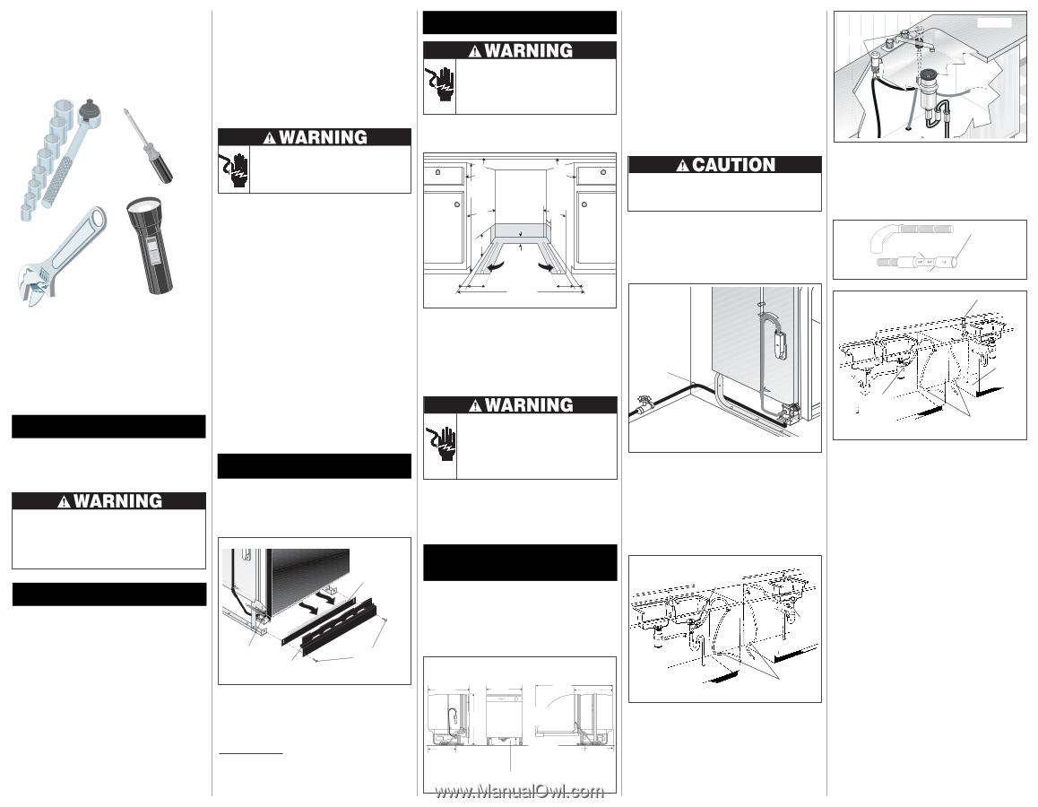
Drain
1.
Review
Figures 5, 6
and
7
to see the different ways to connect
dishwasher to drain system. Choose method that best suits
your need.
2.
If you connect to a sink drain
, entry will need to be above
trap. A “Y” branch tailpiece and connector kit, not included, will
make this method easier and includes all needed fittings and
instructions.
See Figure 5.
5.
Before cutting
drain hose access, check both sides of selected
area to avoid interference. Cut a 2” diameter hole in shaded
area shown in
Figure 2
.
6.
If the cabinet wall is wood, sand edges of hole until smooth and
rounded. If cabinet wall is metal, cover all sharp edges with
electrical or duct tape to avoid cutting drain hose.
Installation Tips
1
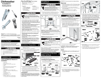
Tools and Materials Needed for
Installation
•
Drill, Electric
•
Driver, Socket
5
/
32
”,
1
/
4
”
,
5
/
16
”
•
Flaring Tool / Tube Cutter (for copper tubing)
•
Flashlight
•
Level
•
Pipe Joint Compound (for iron pipe plumbing) or
Pipe Thread Tape (for sealing threads)
•
Pliers
•
Safety Glasses
•
Saw, Keyhole or
1
/
2
”, 1
1
/
2
”
to 2” Hole Cutters
•
Screw Drivers, Slotted and #2 Phillips
(magnetic tip
preferred)
•
Tape, Electrical or Duct
•
Tape, Measuring
•
Wire Stripper or Utility Knife
•
Wrench, Hex-end
•
Wrenches, 2 Adjustable
(for copper tubing)
or 2 Pipe wrenches
(for iron pipe plumbing)
Electric Shock Hazard
Electrical, water, and drain lines must be confined
to shaded areas in Figure 2.
Electric conductors, water, and drain could be
damaged.
Failure to follow these instructions could result in
fire or electric shock.
NOTE:
If dishwasher is installed at end of a cabinet line, sides
and back must be fully enclosed.
NOTE: You can order a Cabinet Seal Kit (Kit # 154528701) by
contacting your dealer or parts supplier.
This kit provides a
seal between the unit and cabinets once installation is
complete.
(This kit is included on select models).
IMPORTANT: Do not cross drain, water, and electrical lines in
front of dishwasher motor or frame.
4
Connections For Electrical,
Water, and Drain
Right Side
Right Side
Right Side
Right Side
Right Side
Front
Front
Front
Front
Front
Left Side
Left Side
Left Side
Left Side
Left Side
Door in
Door in
Door in
Door in
Door in
open position
open position
open position
open position
open position
Locating the Connections
1.
Review dimensions in
Figure 3
to locate dishwasher’s drain,
water, and electrical connections.
2.
All connections must be made in shaded area in
Figure 2.
25
24
49
1
/
4
”
22
1
/
2
”
33
1
/
2
”
Min.
From rear to
From rear to
From rear to
From rear to
From rear to
center of water
center of water
center of water
center of water
center of water
inlet valve.
inlet valve.
inlet valve.
inlet valve.
inlet valve.
3
3
/
4
”
From floor to
From floor to
From floor to
From floor to
From floor to
water inlet
water inlet
water inlet
water inlet
water inlet
valve.
valve.
valve.
valve.
valve.
Floor Line
Floor Line
Floor Line
Floor Line
Floor Line
Figure 3
Figure 3
Figure 3
Figure 3
Figure 3
Junction Box
Junction Box
Junction Box
Junction Box
Junction Box
(not visible)
(not visible)
(not visible)
(not visible)
(not visible)
17
3
/
4
”
From rear to
From rear to
From rear to
From rear to
From rear to
junction box.
junction box.
junction box.
junction box.
junction box.
3.
Locate water inlet valve behind kickplate on bottom left
underside of unit. The valve has a
3
/
8
” NPT female fitting.
4.
Wrap 90
°
elbow (not included) with pipe thread tape (or apply
joint compound) and thread it into water inlet valve.
5.
Tighten elbow with a wrench, leaving elbow pointing toward
rear
of unit.
To prevent bending of bracket or breaking of valve,
avoid overtightening.
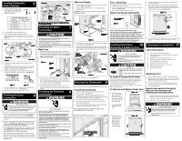
1.
Remove two (2) screws at front of the kickplate assembly using
a #2 Phillips screw driver.
2.
Tilt and pull forward to remove.
See Figure 1.
NOTE:
It is not necessary to remove the outer door for installation.
However, you might find it more convenient to do so. You
can find directions for removing door in Step 10.
Installation Preparation
2
•
Examine dishwasher and locate connections.
See Step 4.
•
Locate dishwasher where there is easy access to drain,
water, and electrical lines. The best location is on either side
of the kitchen sink for access to existing plumbing and ease
in loading dishes.
See Step 4.
•
Electrical, water, and drain connections are not the same for
all age, brands, or models of dishwashers. Check the
location and length of home utilities.
See Step 4.
•
A 15-20 amp, grounded, 120 volt AC only, electrical supply is
required.
See Steps 4 and 8.
•
If dishwasher drain hose will be connected to a food
disposer for the first time, knock out plug located inside
disposer inlet.
See Steps 4 and 6.
•
Kinked water or drain hoses can cause problems.
See Step
6.
•
Dishwashers need to be connected to a hot water supply
with enough water pressure to insure an adequate fill.
See Steps 4 and 7.
•
Each home installation differs.
You will need additional
parts listed above to complete your installation.
See Steps 4 and 7.
•
Flush water line prior to making the final connection to
prevent clogging of dishwasher’s filter screen.
See Step 7.
•
The dishwasher will look, sound, and perform best when
properly leveled.
See Step 5.
(NOTE: If levelers are
removed during installation, make sure the floor is flat and
free of any obstruction.)
•
Anchor the dishwasher.
See Step 9.
Kickplate Assembly
Kickplate Assembly
Kickplate Assembly
Kickplate Assembly
Kickplate Assembly
Figure 1
Figure 1
Figure 1
Figure 1
Figure 1
Bottom Screws
Bottom Screws
Bottom Screws
Bottom Screws
Bottom Screws
(Insulation available
(Insulation available
(Insulation available
(Insulation available
(Insulation available
some models)
some models)
some models)
some models)
some models)
Kickplate
Kickplate
Kickplate
Kickplate
Kickplate
Water Inlet
Water Inlet
Water Inlet
Water Inlet
Water Inlet
Valve
Valve
Valve
Valve
Valve
Entry Must be
Entry Must be
Entry Must be
Entry Must be
Entry Must be
Above Trap
Above Trap
Above Trap
Above Trap
Above Trap
Sink at Left
Sink at Left
Sink at Left
Sink at Left
Sink at Left
Sink at Right
Sink at Right
Sink at Right
Sink at Right
Sink at Right
“Y”
“Y”
“Y”
“Y”
“Y”
Branch
Branch
Branch
Branch
Branch
Tailpiece
Tailpiece
Tailpiece
Tailpiece
Tailpiece
2” Drain Hose Hole
2” Drain Hose Hole
2” Drain Hose Hole
2” Drain Hose Hole
2” Drain Hose Hole
Figure 5
Figure 5
Figure 5
Figure 5
Figure 5
Sink at Right
Sink at Right
Sink at Right
Sink at Right
Sink at Right
Remove
Remove
Remove
Remove
Remove
Knockout
Knockout
Knockout
Knockout
Knockout
Plug in
Plug in
Plug in
Plug in
Plug in
Disposer
Disposer
Disposer
Disposer
Disposer
2” Drain Hose Hole
2” Drain Hose Hole
2” Drain Hose Hole
2” Drain Hose Hole
2” Drain Hose Hole
Figure 7(b)
Figure 7(b)
Figure 7(b)
Figure 7(b)
Figure 7(b)
Parts You Will Need*
(Not Included)
•
Drain Hose Clamp, 1
1
/
4
”
Diameter
• Elbow,
90° with a
3
/
8
” National Pipe Thread
•
Conduit Connector
•
Wire Nuts, two (2) for 12-14 gauge wire
*
If required:
Available at:
•
“Y” Branch Tailpiece and
Plumbing Supply Store
Connector Kit (
See Step 4
)
•
Air Gap Kit (
See Step 4
)
Plumbing Supply Store
•
Fasteners for floor
Hardware Store
anchoring (
See Step 9
)
IMPORTANT:
Disconnect power before starting installation.
Electrical
1.
The dishwasher operates on a 120 volt, 60 Hz electrical supply.
Provide a separate circuit with a fuse or circuit breaker rated for
at least 15 amps (20 amps if connected with disposer) but not
more than 20 amps.
2.
Note the locations of electrical supply and dishwasher’s
electrical junction box on right underside of unit behind kickplate
assembly.
See Figure 3
.
3.
Cut access hole in shaded area shown in
Figure 2
.
4.
Pull electrical cable through hole into installation area.
Water
1.
Determine where you will connect to hot water supply. Review
Figure 3
and note the location of water inlet valve.
Property Damage
Do not use the furnished drain hose or a rubber garden hose
for the water supply line. Either of these hoses can burst.
Flooding may occur and cause property damage.
3.
If you connect to a sink trap
, local codes may require you to
install an air gap kit, (not included). The drain hose will be routed
from dishwasher to air gap inlet as shown in
Figure 6
. An air
gap kit is available from a plumbing supply store.
(If the drain
hose is installed through the floor, an air gap is necessary).
4.
If you connect to a disposer
, the large end of drain hose will fit.
Figure 7(a)
.
The knock out plug must be removed from
inside disposer inlet before making the final fit to drain
hose.
See Figure 7(b).
3
Roughing In
Electric Shock Hazard
Observe all local codes and ordinances for
electrical and plumbing connections. All electrical
and plumbing work should be performed by
qualified persons. Failure to follow this warning
could result in death or serious injury
.
1.
Make sure your location has the right drain, water, and
electrical outlets to make the
connections.
Do not install unit
under a cooktop range. Damage to plastic tub will occur.
90°
90°
2
1
/
2
”
6”
24”
6”
2
1/2
”
2
3/4
”
Hot
Water
Line
Electrical
Wiring
s
s
3”
4”
24”
min.
18”
Electrical, water,
Electrical, water,
Electrical, water,
Electrical, water,
Electrical, water,
and drain lines
and drain lines
and drain lines
and drain lines
and drain lines
must be confined
must be confined
must be confined
must be confined
must be confined
to shaded area.
to shaded area.
to shaded area.
to shaded area.
to shaded area.
Figure 2
Figure 2
Figure 2
Figure 2
Figure 2
Through
Through
Through
Through
Through
Cabinet
Cabinet
Cabinet
Cabinet
Cabinet
2.
Be sure water inlet valve is protected from freezing. If valve
freezes and ruptures, flooding may occur.
3.
Determine amount of tubing needed to connect hot water
supply to the unit’s water inlet valve. Copper tubing must have a
minimum
3
/
8
” OD.
High-pressure and high-temperature rated
plastic tubing with a minimum
inner
diameter of
1
/
4
” may be
used. A shut-off valve installed
outside
dishwasher cabinet is
best.
See Figure 4.
34
1
/
4
” min.
IMPORTANT:
For proper operation and appearance of unit,
cabinet opening should have dimensions as shown in Figure 2.
If unit is to be placed in a corner, there must be at least a 2-inch
side clearance to open door.
2.
Remove any carpet from area to provide motor clearance.
Floor
should be flat and free of any obstruction.
IMPORTANT:
Drain, water, and electrical lines should be
roughed-in before going any further.
Air Gap
Air Gap
Air Gap
Air Gap
Air Gap
Figure 6
Figure 6
Figure 6
Figure 6
Figure 6
INSTALLER
: Leave
Installation Instructions
with owner.
OWNER
: Read your dishwasher
Use and Care Manual.
It contains
important safety information for operating this appliance. It also has
many suggestions for getting the best results from your dishwasher.
Dishwasher
Installation
Instructions
Electric Shock Hazard
Disconnect electrical power at the fuse box or
circuit breaker box before beginning installation.
Failure to follow this warning could result in death
or serious injury
.
Right Side
Right Side
Right Side
Right Side
Right Side
Installation
Installation
Installation
Installation
Installation
Cut for
Cut for
Cut for
Cut for
Cut for
5
/
8
” connection.
” connection.
” connection.
” connection.
” connection.
Drain
Drain
Drain
Drain
Drain
Motor
Motor
Motor
Motor
Motor
End
End
End
End
End
Cut for 3/4” connection.
Cut for 3/4” connection.
Cut for 3/4” connection.
Cut for 3/4” connection.
Cut for 3/4” connection.
Figure 7(a)
Figure 7(a)
Figure 7(a)
Figure 7(a)
Figure 7(a)
Larger end
Larger end
Larger end
Larger end
Larger end
of hose
of hose
of hose
of hose
of hose
fits disposer
fits disposer
fits disposer
fits disposer
fits disposer
inlet fitting.
inlet fitting.
inlet fitting.
inlet fitting.
inlet fitting.
154427301
(07/05)
Printed in U.S.A.
Drain Air Gap
Drain Air Gap
Drain Air Gap
Drain Air Gap
Drain Air Gap
Sink at Left
Sink at Left
Sink at Left
Sink at Left
Sink at Left
Alternate
Alternate
Alternate
Alternate
Alternate
Drain
Drain
Drain
Drain
Drain
Through
Through
Through
Through
Through
Floor into
Floor into
Floor into
Floor into
Floor into
Separate
Separate
Separate
Separate
Separate
Trap
Trap
Trap
Trap
Trap
Drain Hose
Drain Hose
Drain Hose
Drain Hose
Drain Hose
Adjustable Toeplate
Adjustable Toeplate
Adjustable Toeplate
Adjustable Toeplate
Adjustable Toeplate
Cabinet Preparation:
As a precaution, it is recommended, but not required that the
cabinets enclosing all sides of the dishwasher (including the
underside of the countertop) be sealed with an oil based paint
or moisture-proof polyurethane to prevent possible steam/
moisture damage.
*D
IMENSIONS
DO
NOT
INCLUDE
INSULATION