Frigidaire FEF369HS Installation Instructions
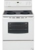
Frigidaire FEF369HS - 30' Electric Range Smooth Top Manual
 |
UPC - 012505548307
View all Frigidaire FEF369HS manuals
Add to My Manuals
Save this manual to your list of manuals |
Frigidaire FEF369HS manual content summary:
- Frigidaire FEF369HS | Installation Instructions - Page 1
to the Consumer Keep these instructions with your owner's guide for future reference. • As when using any appliance generating heat, there are certain safety precautions you should follow. These are listed in the Use & Care Guide, read it carefully. • Be sure your range is installed and grounded - Frigidaire FEF369HS | Installation Instructions - Page 2
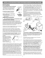
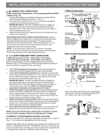
ELECTRICAL CONNECTION REQUIREMENTS - This appliance must be properly installed and range compartment. Excess wire in the range compartment may not allow the Rear Access Cover to be replaced properly and could create a potential electrical hazard if wires become pinched. Connect only as instructed - Frigidaire FEF369HS | Installation Instructions - Page 3
RANGE CORD KIT IS USED, THE INSTALLATION INSTRUCTIONS ARE NOT FOLLOWED OR STRAIN RELIEF BRACKET IS DISCARDED. This appliance 3. ELECTRICAL CONNECTION TO RANGE. The Rear Access Cover Instructions - Refer to Fig.12) Before wiring the range review to the frame of the appliance with the ground screw using - Frigidaire FEF369HS | Installation Instructions - Page 4
replace the rear access cover (See Fig. 9). Grounding Instructions (3-Wire Connections only): A ground strap is installed on this range 5 below. Before wiring the range, review the suggested power source location lead (Green) to the frame of the appliance using the ground screw & plate as shown - Frigidaire FEF369HS | Installation Instructions - Page 5
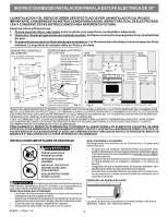
O COBRE DE 0.020". EL ESPACIO LIBRE DE 0" ES EL MINIMO PARA LA PARTE TRASERA DE LA ESTUFA. SIGA TODAS LAS DIMENSIONES INDICADAS ANTERIORMENTE PARA EVITAR DAÑOS DE INSTALACION. Si no se sigue estrictamente la información de este manual, se puede producir un incendio o un choque eléctrico que - Frigidaire FEF369HS | Installation Instructions - Page 6
la pared donde se colocará el costado izquierdo o derecho de la estufa. Si la parte trasera de la estufa será colocada contra la pared o a no más de 1-1/4" marque la ubicación de los agujeros de los tornillos en la pared. Si la parte trasera de la estufa está a más de 1-1/4" de la pared cuando ya - Frigidaire FEF369HS | Installation Instructions - Page 7
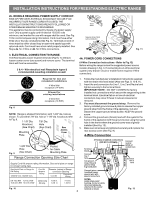
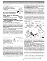
INSTRUCCIONES DE INSTALACION PARA LA ESTUFA ELECTRICA DE 30" Consulte la Tabla del Tamaño de la Abertura de Conexión de la Estufa (Figs. 9 y 10) para la información sobre los amperes del juego de cordón. Los bornes en los extremos de los almabres deben ser de anillo cerrado u horquillas abiertas - Frigidaire FEF369HS | Installation Instructions - Page 8
INSTRUCCIONES DE INSTALACION PARA LA ESTUFA ELECTRICA DE 30" o 4B. CONEXIONES DEL CORDON DE ALIMENTACION Instrucciones para conexión trifilar (para instalaciones existentes SOLAMENTE Consulte la Fig. 13). 1. Siga las instrucciones de instalación del fabricante suministradas con el sujetacable e
-
 1
1 -
 2
2 -
 3
3 -
 4
4 -
 5
5 -
 6
6 -
 7
7 -
8
 |
 |
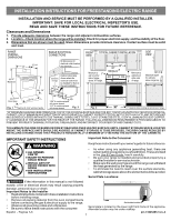
INSTALLATION AND SERVICE MUST BE PERFORMED BY A QUALIFIED INSTALLER.
IMPORTANT: SAVE FOR LOCAL ELECTRICAL INSPECTOR'S USE.
READ AND SAVE THESE INSTRUCTIONS FOR FUTURE REFERENCE.
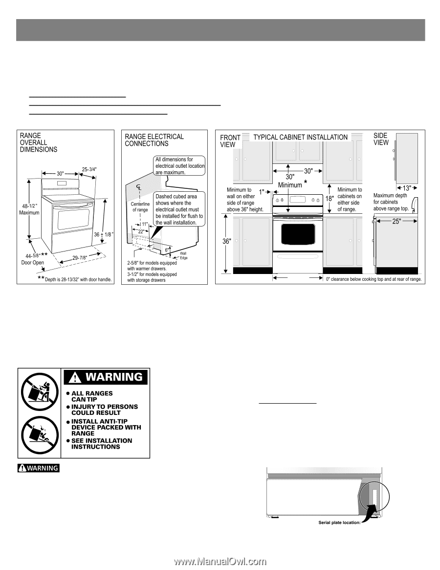
Clearances and Dimensions
1.
Provide adequate clearances between the range and adjacent combustible surfaces.
2.
Location—Check location where the range will be installed. Check for proper electrical supply, and the stability of the floor.
3.
Dimensions that are shown must be used. Given dimensions provide minimum clearance. Contact surface must be solid
and level.
*30" MINIMUM CLEARANCE BETWEEN THE TOP OF THE COOKING SURFACE AND THE
BOTTOM OF AN UNPROTECTED WOOD OR METAL
CABINET; OR 24" MINIMUM WHEN BOTTOM OF WOOD OR METAL CABINET IS PROTECTED BY NOT LESS THAN 1/4" FLAME RETARDANT
MILLBOARD COVERED WITH NOT LESS THAN NO. 28 MSG SHEET STEEL, 0.015" STAINLESS STEEL, 0.024" ALUMINUM OR 0.020" COPPER.
0" CLEARANCE IS THE MINIMUM FOR THE REAR OF THE RANGE. FOLLOW ALL DIMENSION REQUIREMENTS PROVIDED ABOVE TO
PREVENT PROPERTY DAMAGE, POTENTIAL FIRE HAZARD, AND INCORRECT COUNTERTOP AND CABINET CUTS.
TO ELIMINATE THE RISK OF BURNS OR FIRE BY REACHING OVER HEATED SURFACE UNITS, CABINET STORAGE SPACE LOCATED
ABOVE THE SURFACE UNITS SHOULD BE AVOIDED. IF CABINET STORAGE IS TO BE PROVIDED, THE RISK CAN BE REDUCED BY
INSTALLING A RANGE HOOD THAT PROJECTS HORIZONTALLY A MINIMUM OF 5" BEYOND THE BOTTOM OF THE CABINETS.
p/n 316454912 rev A
If the information in this manual is not followed
exactly, a fire or electrical shock may result causing property
damage, personal injury or death.
Important Notes to the Installer
•
Read all instructions contained in these installation instructions
before installing range.
•
Remove all packing material from the oven compartments
before connecting the gas & electrical supply to the range.
•
Observe all governing codes and ordinances.
•
Be sure to leave these instructions with the consumer.
Fig. 1
Fig. 2
Fig. 3
30"
Important Note to the Consumer
Keep these instructions with your owner's guide for future reference.
•
As when using any appliance generating heat, there are
certain safety precautions you should follow. These are listed
in the
Use & Care Guide, read it carefully.
•
Be sure your range is installed and grounded properly by a
qualified installer or service technician.
•
Make sure the wall coverings around the range can withstand
the heat generated by the range.
•
To eliminate the need to reach over the surface elements,
cabinet storage space above the elements should be avoided.
IMPORTANT SAFETY INSTRUCTIONS
Serial plate is located on the lower right front frame of the appliance.
Alternate location may be under cooktop.
Serial Plate Locations:
INSTALLATION INSTRUCTIONS FOR FREESTANDING ELECTRIC RANGE
1
Español - Páginas 5-8