Frigidaire FFTR1835VB Wiring Diagram
Frigidaire FFTR1835VB Manual
 |
View all Frigidaire FFTR1835VB manuals
Add to My Manuals
Save this manual to your list of manuals |
Frigidaire FFTR1835VB manual content summary:
- Frigidaire FFTR1835VB | Wiring Diagram - Page 1
psig Wattage 93W 88W 93W Amps 0.74 to 0.94 A Base Voltage 115V Refrigerant Charge 40 g Cabinet Size: 18' CD 18´, SD 18´, SD 20 ON. Manual Water Fill: Press and hold the TEST/SERVICE button for 3+ seconds. Adjust Water Fill Size: Press and hold the POWER and TEST/SERVICE buttons together - Frigidaire FFTR1835VB | Wiring Diagram - Page 2
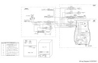
Wiring Diagram A15972401
-
 1
1 -
 2
2
 |
 |
ICE MAKER INFORMATION
Turn the IM ON and OFF:
Press and hold the POWER button for ½ second to turn the IM ON and OFF. When the IM is ON, the Power buttin will be
illuminated solid green
Test Cycling:
Press and release the TEST/SERVICEbutton to start the self-diagnostic function. The tray will perform two rotations. The ice level arm must be held so that it does not drop during the first rotation (simulating full ice bin). Once the
tray returns to the Home position, the arm can be released. Allow the arm to drop normally during the the
second rotation (simulating empty ice bin). Once the tray returns Home after the second rotation, the POWER button will change back to solid green if no errors were detected during the test. This means the IM operates properly. If errors are de
-
tected at any time during the test, the test will stop immediately and the POWER button will blink rapidly continuously. In this case, there is some internal failure of the IM.
NOTE: If the arm is not held during the first rotation, the IM will
indicate a failure falsely.
To run the test again to verify, the IM must be turned OFF and back ON.
Manual
Water Fill:
Press and hold the TEST/SERVICE button for 3+ seconds.
Adjust Water Fill Size:
Press and hold the POWER and TEST/SERVICE buttons together for 3 seconds. The POWER button will blink to show the current setting.
1 blink = small, 2 blinks = med, 3 blinks = large, 4 blinks = extra large. Press the TEST/SERVICE button to advance to the next level. When at extra large, the next press goes back to small. The factory default is small.
IMPORTANT
PLEASE RETURN THIS SHEET TO ITS ORIGINAL LOCATION.
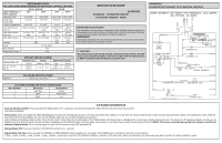
ICE MAKER SPECIFICATIONS
Electrical
115 vac (127 vac max)
60 Hertz
PERFORMANCE DATA
NO LOAD & NO DOOR OPENINGS AT MID-POINT CONTROL SETTING
CD 18´ & SD 18´
SD 20´
Type A With Run/
Start Capacitor
70°F
90°F
70°F
90°F
Operating Time
24 to 30%
42 to 48%
24 to 30%
40 to 46%
Fresh Food
Temperature
33 to 39
34 to 40
33 to 39
34 to 40
Freezer Temperature
4° to -4°F
2° to -6°F
2 to -6
0 to -8
Low Side Pressure
(cut-in)
0.26 to 1.22 psig
-0.37 to 0.97
psig
-0.8 to 0.36
psig
-1.69 to
0.43 psig
Low Side Pressure
(cut-out)
-6.92 to -7.33
psig
-6.63 to -7.23
psig
-7.1 to -7.5
psig
-6.59 to
-7.23 psig
High Side Pressure
38 to 41 psig
53 to 59 psig
43 to 46
psig
60 to 63
psig
Wattage
93W
88W
93W
Amps
0.74 to 0.94 A
Base Voltage
115V
Refrigerant Charge
40 g
DEFROST SPECIFICATIONS
Cabinet Size: 18'
Thermal Fuse
Heater
Defrost Thermostat
Cut-out
Watts
Ohms
Open
Closed
CD 18´, SD 18´,
SD 20´
161.6°F
(72°C)
178
79.7
50°F
(10°C)+/-3
28.4°F
(-2°C)+/-3
ICE MAKER CONNECTOR PLUG CONNECTIONS
Wire Number
Wire Color
Connects to:
1
Light Blue
Neutral
2
Yellow
Water Valve
3
Black
Line
SERVICE DATA SHEET
A16330301
STANDARD - AUTOMATIC DEFROST
TOP MOUNT FREEZER - R600a
IMPORTANT SAFETY NOTE
The information provided herein is designed to assist qualified repair personnel only.
Untrained persons should not attempt to make repairs due to the possibility of electrical
shock. Disconnect power cord before servicing this appliance.
IMPORTANT
If any green grounding wires are removed during servicing, they must be returned to
their original position and properly secured.
CAUTION
All electrical parts and wiring must be shielded from torch flame. DO NOT
allow torch to touch insulation; it will char at 200°F and flash ignite (burn)
at 500°F. Excessive heat will distort the plastic liner.