Frigidaire FGEF306TMB Installation Instructions (All Languages)
Frigidaire FGEF306TMB Manual
 |
View all Frigidaire FGEF306TMB manuals
Add to My Manuals
Save this manual to your list of manuals |
Frigidaire FGEF306TMB manual content summary:
- Frigidaire FGEF306TMB | Installation Instructions (All Languages) - Page 1
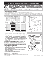
to the Consumer Keep these instructions with your Use and Care Guide for future reference. Printed in Canada 1 Terminal Block Location BACK VIEW All dimensions for electrical outlet location are maximum. Cubed area shows where the electrical outlet must be installed for the range to be flush to - Frigidaire FGEF306TMB | Installation Instructions (All Languages) - Page 2
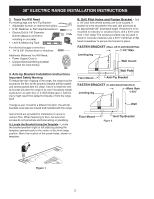
location, the anti-tip brackets must also be moved and installed with the range. Instructions are provided for installation in wood or cement floor. When fastening to floor, be sure that screws do not penetrate electrical wiring or plumbing. A. Locate the Bracket Using the Template - Locate - Frigidaire FGEF306TMB | Installation Instructions (All Languages) - Page 3
30" ELECTRIC RANGE INSTALLATION INSTRUCTIONS C. Level and position the range - Slide range to its final position. Insert the range leveling leg in the anti-tip bracket. Visually verify if the anti-tip bracket is engaged. Lower the range by adjusting the 4 leveling legs alternatively until the range - Frigidaire FGEF306TMB | Installation Instructions (All Languages) - Page 4
required, punch out the knockout. Risk of fire or electrical shock exists if an incorrect size range cord kit is used, the Installation Instructions are not followed, or the strain relief bracket is discarded. For mobile homes, new installations or recreational vehicles, use only a power supply kit - Frigidaire FGEF306TMB | Installation Instructions (All Languages) - Page 5
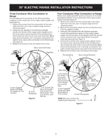
30" ELECTRIC RANGE INSTALLATION INSTRUCTIONS Three Conductor Wire Connection to Range If local codes permit connection of Colored Terminal Terminal Block Cord Mounting Plate Red Wire Black Wire A User Supplied Strain-relief Must Be Installed at This Location. Neutral (White Wire) Grounding - Frigidaire FGEF306TMB | Installation Instructions (All Languages) - Page 6
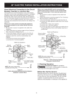
30" ELECTRIC RANGE INSTALLATION INSTRUCTIONS Direct Electrical Connection to the Circuit Breaker, Fuse Box You Call for Service Read the Before You Call for Service Checklist and operating instructions in your Use and Care Guide. It may save you time and expense. The list includes common occurrences - Frigidaire FGEF306TMB | Installation Instructions (All Languages) - Page 7
lida y estar a nivel. vista TYPICAL CABINET INSTALLATION frontal Vista VISTA Lado FRONTAL 29-7/8" 25-3/4" de cobre. 0" es el espacio mínimo para la parte trasera de la estufa. Siga todos los requerimientos de medidas el Manual del usuario para referencia futura. Impreso en Canada 318201729 (1108 - Frigidaire FGEF306TMB | Installation Instructions (All Languages) - Page 8
fijación colocando la plantilla simétricamente a la línea central de la apertura. El soporte antivuelco puede instalarse en el lado izquierdo o derecho en la parte posterior de la estufa. Marque la ubicación de los agujeros de tornillos come se muestra en el papel. B. Perforación de agujeros piloto - Frigidaire FGEF306TMB | Installation Instructions (All Languages) - Page 9
INSTRUCCIONES PARA INSTALACIÓN DE LA ESTUFA ELÉCTRICA DE 30" C. Nivele la cocina y coloque la cocina en su lugar. - Deslice la estufa a su lugar. Colocar la pata niveladora dentro del braquete anti-basculante. Verifique visualmente que los soportes antivuelco estén correctamente enganchados ( - Frigidaire FGEF306TMB | Installation Instructions (All Languages) - Page 10
a tierra por un técnico calificado, de acuerdo con el National Electric Code (Código Nacional de Electricidad) ANSI/NFPA No. 70 -última tuercas que aseguran la conexión de la cocina al bloque terminal cuando esté instalándola. El corte o la perdida de corriente eléctrica puede ocurrir. Peligro - Frigidaire FGEF306TMB | Installation Instructions (All Languages) - Page 11
ón del conductor a tierra del armazón al alambre neutral del cable de bronce del suministro eléctrico (vea figura 6). 1. Retire los tornillos de la parte baja de la cubierta del cable trasero (cubierta de acceso), para tener acceso al bloque de conexión del borne terminal. 2. Utilizar los tuercas - Frigidaire FGEF306TMB | Installation Instructions (All Languages) - Page 12
de quitar la banda de puesta a tierra provista. Figura 9 Antes de llamar al servicio Lea la sección Lista de Antes de llamar en su Manual del Usuario. Esto le podrá ahorrar tiempo y gastos. Esta lista incluye ocurrencias comunes que no son el resultado de defectos de materiales o fabricación de
-
 1
1 -
 2
2 -
 3
3 -
 4
4 -
 5
5 -
 6
6 -
 7
7 -
8
-
9
-
10
-
11
-
12
 |
 |

30" ELECTRIC RANGE INSTALLATION INSTRUCTIONS
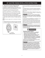
1. Clearances and Dimensions
a. Provide adequate clearances between the range and adjacent combustible surfaces.
b. Location—Check location where the range will be installed. Check for proper electrical supply and the stability of floor.
c. Dimensions that are shown must be used. Given dimensions provide minimum clearance. Contact surface must
be solid and level.
*
30" minimum clearance between the top of the cooking surface
and the bottom of an unprotected wood or metal cabinet; or 24 "
minimum when bottom of wood or metal cabinet is protected by not
less than ¼" flame retardant millboard covered with not less than
no. 28 MSG sheet steel, 0.015" stainless steel, 0.024" aluminum
or
0.020" copper. The minimum clearance is 0" for the rear of the
range. Follow all dimension requirements provided above to prevent
property damage, potential fire hazard, and incorrect countertop
and cabinet cuts.
Avoid locating cabinet storage space above the surface units
to eliminate the possibility of cabinets catching on fire, or
personal burns from reaching for the cabinets over the heated
units. If cabinet storage is to be provided, risk can be reduced by
installing a range hood that projects horizontally a minimum of
5" beyond the bottom of the cabinets.
Printed in Canada
318201729 (1108) Rev. B
FRONT
VIEW
BACK
VIEW
FRONT
VIEW
TYPICAL CABINET INSTALLATION
SIDE
VIEW
Important Notes to the Installer
1.
Read all instructions contained in these installation instructions
before installing the appliance.
2.
Remove all packing material before connecting the electrical
supply to the appliance.
3.
Observe all governing codes and ordinances.
4.
Be sure to leave these instructions with the consumer.
Important Note to the Consumer
Keep these instructions with your Use and Care Guide for future reference.
All dimensions for
electrical outlet
location are maximum.
Cubed area shows
where the electrical
outlet must be
installed for the
range to be flush to
the wall.
Wall
Edge
Terminal
Block
Location
29-7/8”
25-3/4”
49”
Maximum
42”
Door open
30”
36
1/8”
INSTALLATION AND SERVICE MUST BE PERFORMED BY A QUALIFIED
INSTALLER. IMPORTANT: SAVE FOR LOCAL ELECTRICAL INSPECTOR'S
USE. READ AND SAVE THESE INSTRUCTIONS FOR FUTURE REFERENCE.
FOR YOUR SAFETY: Do not store or use gasoline or other
flammable vapors and liquids in the vicinity of this or any other appliance.
United States