Frigidaire FGET3066UF Wiring Diagram
Frigidaire FGET3066UF Manual
 |
View all Frigidaire FGET3066UF manuals
Add to My Manuals
Save this manual to your list of manuals |
Frigidaire FGET3066UF manual content summary:
- Frigidaire FGET3066UF | Wiring Diagram - Page 1
and satisfactory manner. 2. Before servicing or moving an appliance, remove power cord from electric outlet, trip circuit breaker to Off, or remove fuse. 3. Never interfere with the proper installation of any safety device. 4. Use only replacement parts specified for this appliance. Substitutions - Frigidaire FGET3066UF | Wiring Diagram - Page 2
that does not 2. match the key map. 3. Verify the unit has the proper oven user interface board and touch panel, based on the model number and parts catalog. Replace the oven user interface board. If the problem persists replace the touch panel. Data written to non-volatile memory has failed - Frigidaire FGET3066UF | Wiring Diagram - Page 3
2. Avant de procéder au service d'entretien ou de déplacer tout alimentation en gaz. 3. N'entravez jamais l'installation adéquate de tout dispositif de sé entretien pour obtenir des instructions sur l'ajustement des temp K2 FOUR SUPÉRIEUR DLB LIGNE DOUBLE INTERROMPUE L1 ÉLÉMENT DE GRIL. FOUR - Frigidaire FGET3066UF | Wiring Diagram - Page 4
configurée correctement. Remplacez la carte interface usager. Assurez-vous d'installer la dernière version disponible pour ce modèle. Emballement panneau tactile. À l'aide du numéro de modèle et du catalogue de service, vérifiez si l'appareil a la bonne carte interface usager et le bon panneau
-
 1
1 -
 2
2 -
 3
3 -
 4
4
 |
 |
NOTICE:
This service data sheet is intended for use by persons having electrical and me-
chanical training and a level of knowledge of these subjects generally considered acceptable
in the appliance repair trade. The manufacturer cannot be responsible, nor assume any
liability, for injury or damage of any kind arising from the use of this data sheet.
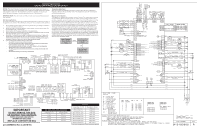
IMPORTANT NOTE:
This unit includes an EOC (electronic oven control). This board is not
field-repairable.
Safe Servicing Practices
To avoid the possibility of personal injury and/or property damage, it is important that safe ser-
vicing practices be observed. The following are some, but not all, examples of safe practices.
1.
Do not attempt a product repair if you have any doubts as to your ability to complete it
in a safe and satisfactory manner.
2.
Before servicing or moving an appliance, remove power cord from electric outlet, trip
circuit breaker to Off, or remove fuse.
3.
Never interfere with the proper installation of any safety device.
4.
Use only replacement parts specified for this appliance. Substitutions may not comply
with safety standards set for home appliances.
5.
Grounding: The standard color coding for safety ground wires is green or green with
yellow stripes. Ground leads are not to be used as current carrying conductors. It is
extremely important that the service technician reestablish all safety grounds prior to
completion of service. Failure to do so will create a potential hazard.
6.
Prior to returning the product to service, ensure that:
•
All electric connections are correct and secure.
•
All electrical leads are properly dressed and secured away from sharp edges,
high-temperature components, and moving parts.
•
All uninsulated electrical terminals, connectors, heaters, etc. are adequately
spaced away from all metal parts and panels.
•
All safety grounds (both internal and external) are correctly and securely reas-
sembled.
•
All panels are properly and securely reassembled.
IMPORTANT
DO NOT REMOVE THIS BAG
OR DESTROY THE CONTENTS
WIRING DIAGRAMS AND SERVICE
INFORMATION
ENCLOSED
REPLACE CONTENTS IN BAG
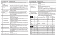
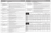
Resistance (ohms)
1000 ± 4.0
1091 ± 5.3
1453 ± 8.9
1654 ± 10.8
1852 ± 13.5
2047 ± 15.8
2237 ± 18.5
2697 ± 24.4
Open circuit/infinite resistance
RTD SCALE
Temperature °F (°C)
32 ± 1.9 (0 ± 1.0)
75 ± 2.5 (24 ± 1.3)
250 ± 4.4 (121 ± 2.4)
350 ± 5.4 (177 ± 3.0)
450 ± 6.9 (232 ± 3.8)
550 ± 8.2 (288 ± 4.5)
650 ± 9.6 (343 ± 5.3)
900 ± 13.6 (482 ±7.5)
Probe circuit to case ground
p/n A00980650 Rev A (2018/10)
SERVICE DATA SHEET
ELECTRIC OVEN WITH MODULAR OVEN CONTROLS
Temperature Adjustment
Refer to the Use & Care Manual for directions on how to adjust the oven temperatures.
Changing calibration affects all baking modes. The adjustments made will not change the
self-cleaning temperature.
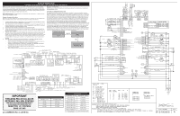
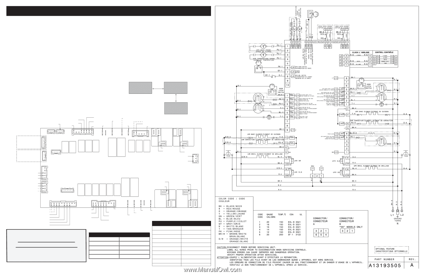
Modular Control Systems
This appliance is equipped with a modular system of controls. The modular system consists
of various boards which communicate with one another to drive cooking functions. Oven
functions, if available, operate through an oven user interface (UI or UIB) and an oven relay
board. Cooktop functions, if available, operate through a cooktop UI/UIB and a cooktop
relay board. There may be additional boards which work within the system to drive specific
functions (refer to the schematics and diagrams and this sheet). Low voltage operating and
communications power for the modular boards is provided through the wiring schemes.
The boards that generate low voltage operating and communications power depend upon
the individual control system (refer to the schematics and diagrams on this sheet). These
voltages are only the operational voltages. Do not use these voltages as confirmation of
communication between the boards. Communication occurs through software programming
on each board. This communication is not detectable by volt ohmmeters. The programming
is self-monitored and the UI displays will show error codes based on detected failures. The
individual boards are not field repairable. See the schematics and diagrams included on this
sheet for more unit-specific details.
MEAT PROBE TEMPERATURE VS RESISTANCE
Temperature °F (°C)
Resistance (Kohm)
77 (25)
50.0 ± 7%
122 (50)
18.0 ± 4.9%
176 (80)
6.3 ± 3.3%
212 (100)
3.4 ± 4.6%
1
1
1
1
1
1
1
1
1
1
1
1
1
J4
J3
J13 UPPER OVEN
J12 UPPER OVEN
J11
OVC POWER
(POWER TO BOARD)
J5 UPPER OVEN
J1
J25
LOWER
OVEN
J26
LOWER
OVEN
J10 LOWER OVEN
TO TANGENTIAL FAN
SPEED SENSOR
(optional)
J2
DIAGNOSTICS
J14 LOWER OVEN
K9
K3
K4
K5
K6
K8
K13
K12
K11 K10
K16
K17
K1
UPPER
OVEN
K19
K18
K20
K21
K22
K23
K14
LOWER
OVEN
P1
P5
P4
P3
P13
P12
P2
P7
P8
P9
NEUTRAL
L1
PROGRAMMING
HEADER
L2 OUT/THERM
DLB
L2 IN
BROIL
LOWER OVEN
NEUTRAL
CONVECTION ELEMENT - LOWER OVEN (OPT)
CONV ELEMENT
LOWER OVEN
L1
BAKE ELEMENT - LOWER OVEN
BAKE ELEMENT
LOWER OVEN
L1
COOLING FAN
LOW SPEED
CONVECTION
FAN LOW
LATCH MOTOR
OVEN LIGHT
COOLING FAN
HIGH SPEED
CONVECTION
FAN HIGH
MEAT PROBE (OPT)
TEMPERATURE PROBE
MEAT PROBE (OPT)
TEMPERATURE PROBE
MEAT PROBE (OPT)
MEAT PROBE (OPT)
K15
LOWER
OVEN
TEMPERATURE PROBE
TEMPERATURE PROBE
LATCH MOTOR SWITCH
DOOR SWITCH
COMMON
LATCH MOTOR SWITCH
COMMON
DOOR SWITCH
LOWER OVEN RELAYS
LATCH
MOTOR
CONV FAN
HIGH
CONV
FAN LOW
COOL FAN
HIGH
COOL
FAN LOW
OVEN
LIGHT
J9 UPPER OVEN
TO COOLING FAN
SPEED SENSOR
(optional)
J3 COMMUNICATION
TO USER INTERFACE BOARD
MARS BOARD
L1
COOLING FAN
LOW SPEED
CONVECTION
FAN LOW
LATCH MOTOR
OVEN
LIGHT
COOLING FAN
HIGH SPEED
CONVECTION FAN HIGH SPEED
L1
BAKE
ELEMENT
UPPER
OVEN
CONVECTION ELEMENT
UPPER OVEN (OPT)
L1
NEUTRAL
SELF CLEAN CATALYST (OPT)
UPPER OVEN RELAYS
UPPER OVEN RELAYS
LATCH
MOTOR
CONV
FAN LOW
COOL FAN
HIGH
COOL
FAN LOW
OVEN
LIGHT
BAKE ELEMENT
UPPER OVEN
CONV ELEMENT
UPPER OVEN
CONV FAN
HIGH
SELF CLEAN
CATALYST
(optional)
K2
UPPER
OVEN
DLB
L2 OUT/THERM
L2 IN
BROIL
UPPER OVEN
L1
L1
OVEN CONTROL
RELAY BOARD
(OVC)
TOUCH PANEL
(BENDER HMI)
OVEN CONTROL
(MARS)
MACS
I2C