Frigidaire FGID2476SF Installation Instructions
Frigidaire FGID2476SF Manual
 |
View all Frigidaire FGID2476SF manuals
Add to My Manuals
Save this manual to your list of manuals |
Frigidaire FGID2476SF manual content summary:
- Frigidaire FGID2476SF | Installation Instructions - Page 1
best results from your dishwasher. Before You Begin Read all instructions before installing dishwasher. For your safety, please read and observe all safety instructions. This guide 8 ) • Air Gap Kit (See Step 8 ) All the parts can be found at local hardware, electrical and plumbing supply stores. - Frigidaire FGID2476SF | Installation Instructions - Page 2
injury. Failure to follow these instructions could result in death or serious injury. 0 Right Side Installation Figure 13( 3. If you connect to a sink trap,local codes may require you to install an air gap kit, (not included). The drain hose will be routed from dishwasher to air gap inlet as
-
 1
1 -
 2
2
 |
 |
Di
shwasher
CD.808
936
695
Installation
Instructions
INSTALLER:
Leave
Installation
Instructions
with
owner.
OWNER:
Read
your
dishwasher
Use
and
Care
Manual.
It
contains
important
safety
information
for
operating
this
appliance.
It
also
has
many
suggestions
for
getting
the
best
results
from
your
dishwasher.
Before
You
Begin
Read
all
instructions
before
installing
dishwasher.
For
your
safety,
please
read
and
observe
all
safety
instructions.
This
guide
will
help
you
anticipate
drain,
water,
and
electrical
connections,
and
help
you
select
the
best
location
for
the
dishwasher.
The
dishwasher
is
provided
with
water
heating
feature.
The
dishwasher
is
intended
for
connection
to
hot
water
supply.
AWARNING
Tip
Over
Hazard
Do
not
use
dishwasher
until
completely
installed.
Do
not
push
down
on
open
door.
Failure
to
follow
this
warning
can
result
in
serious
injury.
AWARNING
Cut
Hazard
To
prevent
serious
injury
from
sharp
edges,
wear
work
gloves
when
handling,
unpacking
or
disassembling
unit.
Installation
Tips
1
Parts
Included:
2
2
x2
Tools
and
Materials
Needed
for
Installation
(Not
Included)
•
Drill,
Electric
•
Driver,
Socket
5
/
3
2
,
1
/
4
,
5
/
1
6"
•
Flaring
Tool
/
Tube
Cutter
(for
copper
tubing)
•
Flashlight
•
Level
•
Pipe
Joint
Compound
(for
iron
pipe
plumbing)
or
Pipe
Thread
Tape
(for
sealing
threads)
•
Pliers
•
Safety
Glasses
•
Saw,
Keyhole
or
1
/
2
",
1
1
/
2
"
to
2"
Hole
Cutters
•
Screw
Drivers,
Slotted
and
02
Phillips
(magnetic
tip
preferred)
•
Work
gloves
•
Tape,
Electrical
or
Duct
•
Measuring
Tape
•
Wire
Stripper
or
Utility
Knife
•
Wrench,
Hex
-end
•
Wrenches,
2
Adjustable
(for
copper
tubing)
or
2
Pipe
wrenches
(for
iron
pipe
plumbing)
Parts
You
Will
Need*(Not
Included)
•
Drain
Hose
Clamp,
1
1
/
4
"
(3,1
cm)
Diameter
•
Brass
Elbow,
90°
with
a
3
/
4
"
(
0
2
cm
)-11.5
NH
to
3
/
8
"
(
0
2
cm
)
NPT
Compression
fitting
•
Conduit
Connector
(UL
Listed)
•
Wire
Nuts,
three
(3)
for
12-14
gauge
wire
(UL
Listed)
*If
required:
•
"Y"
Branch
Tailpiece
and
Connector
Kit
(See
Step
8
)
•
Air
Gap
Kit
(See
Step
8
)
All
the
parts
can
be
found
at
local
hardware,
electrical
and
plumbing
supply
stores.
AWARNING
Electric
Shock
Hazard
Disconnect
electrical
power
at
the
fuse
box
or
circuit
breaker
box
before
beginning
installation.
Failure
to
follow
this
warning
could
result
in
death
or
serious
injury.
Installation
Preparation
2
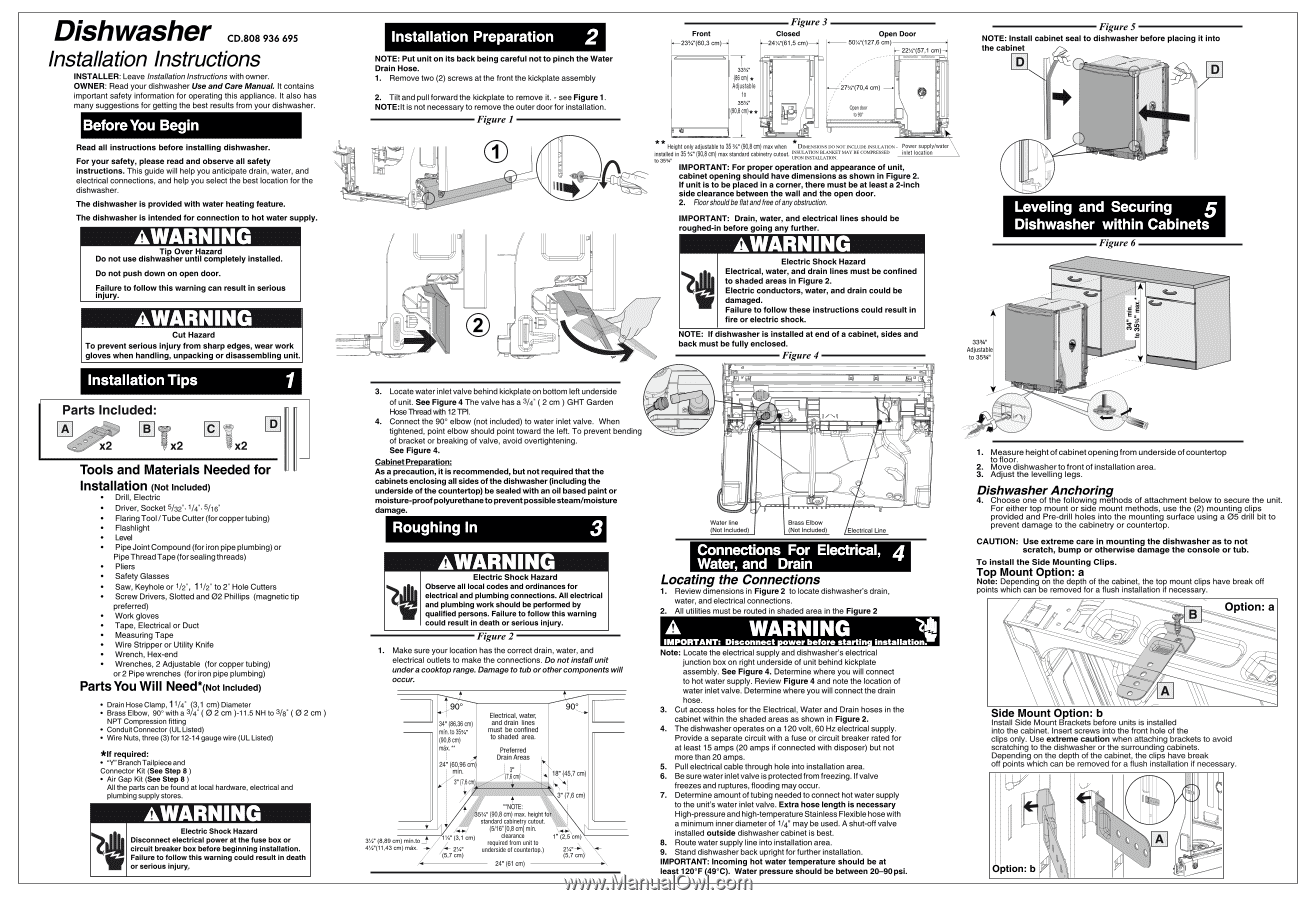
NOTE:
Put
unit
on
its
back
being
careful
not
to
pinch
the
Water
Drain
Hose.
1.
Remove
two
(2)
screws
at
the
front
the
kickplate
assembly
2.
Tilt
and
pull
forward
the
kickplate
to
remove
it.
-
see
Figure
1.
NOTE:It
is
not
necessary
to
remove
the
outer
door
for
installation.
Figure
1
1
I
3.
Locate
water
inlet
valve
behind
kickplate
on
bottom
left
underside
of
unit.
See
Figure
4
The
valve
has
a
3
/
4
"
(
2
cm
)
GHT
Garden
Hose
Thread
with
12
TPI.
4.
Connect
the
90°
elbow
(not
included)
to
water
inlet
valve.
When
tightened,
point
elbow
should
point
toward
the
left.
To
prevent
bending
of
bracket
or
breaking
of
valve,
avoid
overtightening.
See
Figure
4.
Cabinet
Preparation:
As
a
precaution,
it
is
recommended,
but
not
required
that
the
cabinets
enclosing
all
sides
of
the
dishwasher
(including
the
underside
of
the
countertop)
be
sealed
with
an
oil
based
paint
or
moisture
-proof
polyurethane
to
prevent
possible
steam/moisture
damage.
Roughing
In
3
AWARNING
Electric
Shock
Hazard
Observe
all
local
codes
and
ordinances
for
electrical
and
plumbing
connections.
All
electrical
and
plumbing
work
should
be
performed
by
qualified
persons.
Failure
to
follow
this
warning
could
result
in
death
or
serious
injury.
Figure
2
1.
Make
sure
your
location
has
the
correct
drain,
water,
and
electrical
outlets
to
make
the
connections.
Do
not
install
unit
under
a
cooktop
range.
Damage
to
tub
or
other
components
will
occur.
90
°
34"
(86,36
cm)
min.
to
35
3
/
4
"
(90,8
cm)
max.
**
24'
(60,96
cm)
min.
3"
(7,6
cm)
7(r
/
3W
(8,89
cm)
min.to
4W(11,43
cm)
max.
Electrical,
water,
and
drain
lines
must
be
confined
to
shaded
area.
Preferred
Drain
Areas
3
,,
(7,6
cm)
**N0M
35
3
/
4
"
(90,8
cm)
max.
height
for
standard
cabinetry
cutout.
(5/16"
[0,8
cm]
min.
clearance
required
from
unit
to
2
1
/
4
"
underside
of
countertop.)
(5,7
cm)
A4-0.7/
1W
(3,1
cm)
24"
(61
cm)
90
°
18"
(45,7
cm)
3"
(7,6
cm)
\-4-mo\
1"
(2,5
cm)
2
1
/
4
"
-0
'
(5,7
cm)
Front
4
23
3
/
4
"(60,3
33%"
(86
cm)
*
Adjustable
to
35%"
(90,8
cm)
**
•
Figure
3
Closed
24W(61,5
cm)
0
el
Lel
sr
-
rft
0
Open
Door
50%"(127,6
cm)
H
22W(57,1
cm
/
27%"(70,4
cm)
Open
door
to
90°
n
I0
e
()
S
**
Height
only
adjustable
to
35
3
/
4
"
(90,8
cm)
max
when
*
DIMENSIONS
DO
NOT
IN
CLUDE
INSULATION
-
Power
supply/water
installed
in
35
3
/
4
"
(90,8
Cm)
max
standard
cabinetry
cutout.
INSULATION
BLANKET
MAY
BE
COMPRESSED
inlet
location
to
35
3
/
4
"
UPON
INSTALLATION.
IMPORTANT:
For
proper
operation
and
appearance
of
unit,
cabinet
opening
should
have
dimensions
as
shown
in
Figure
2.
If
unit
is
to
be
placed
in
a
corner,
there
must
be
at
least
a
2
-inch
side
clearance
between
the
wall
and
the
open
door.
2.
Floor
should
be
flat
and
free
of
any
obstruction.
IMPORTANT:
Drain,
water,
and
electrical
lines
should
be
roughed
-in
before
going
any
further.
AWARNING
Electric
Shock
Hazard
Electrical,
water,
and
drain
lines
must
be
confined
to
shaded
areas
in
Figure
2.
Electric
conductors,
water,
and
drain
could
be
damaged.
Failure
to
follow
these
instructions
could
result
in
fire
or
electric
shock.
NOTE:
If
dishwasher
is
installed
at
end
of
a
cabinet,
sides
and
back
must
be
fully
enclosed.
Figure
4
In!
L.
k
i‘
Water
line
(Not
Included)
Brass
Elbow
(Not
Included)
4+
Electrical
Line
Connections
For
Electrical,
4
Water,
and
Drain
Locating
the
Connections
1.
Review
dimensions
in
Figure
2
to
locate
dishwasher's
drain,
water,
and
electrical
connections.
2.
All
utilities
must
be
routed
in
shaded
area
in
the
Figure
2
Ci)
A
WARNING
IMPORTANT:
Disconnect
ower
before
startin
installation.
Note:
Locate
the
electrical
supply
and
dishwasher's
electrical
junction
box
on
right
underside
of
unit
behind
kickplate
assembly.
See
Figure
4.
Determine
where
you
will
connect
to
hot
water
supply.
Review
Figure
4
and
note
the
location
of
water
inlet
valve.
Determine
where
you
will
connect
the
drain
hose.
3.
Cut
access
holes
for
the
Electrical,
Water
and
Drain
hoses
in
the
cabinet
within
the
shaded
areas
as
shown
in
Figure
2.
4.
The
dishwasher
operates
on
a
120
volt,
60
Hz
electrical
supply.
Provide
a
separate
circuit
with
a
fuse
or
circuit
breaker
rated
for
at
least
15
amps
(20
amps
if
connected
with
disposer)
but
not
more
than
20
amps.
5.
Pull
electrical
cable
through
hole
into
installation
area.
6.
Be
sure
water
inlet
valve
is
protected
from
freezing.
If
valve
freezes
and
ruptures,
flooding
may
occur.
7.
Determine
amount
of
tubing
needed
to
connect
hot
water
supply
to
the
unit's
water
inlet
valve.
Extra
hose
length
is
necessary
High-pressure
and
high
-temperature
Stainless
Flexible
hose
with
a
minimum
inner
diameter
of
1
/
4
"
may
be
used.
A
shut-off
valve
installed
outside
dishwasher
cabinet
is
best.
8.
Route
water
supply
line
into
installation
area.
9.
Stand
dishwasher
back
upright
for
further
installation.
IMPORTANT:
Incoming
hot
water
temperature
should
be
at
least
120°F
(49°C).
Water
pressure
should
be
between
20-90
psi.
Figure
5
NOTE:
Install
cabinet
seal
to
dishwasher
before
placing
it
into
the
cabinet
In,
Leveling
and
Securing
Dishwasher
within
Cabinets
33
3
/
4
"
Adjustable
to
35
3
A"
Figure
6
g
1.
Measure
height
of
cabinet
opening
from
underside
of
countertop
to
floor.
2.
Move
dishwasher
to
front
of
installation
area.
3.
Adjust
the
levelling legs.
Dishwasher
Anchoring
4.
Choose
one
of
the
following
methods
of
attachment
below
to
secure
the
unit.
For
either
top
mount
or
side
mount
methods,
use
the
(2)
mounting
clips
provided
and
Pre
-drill
holes
into
the
mounting
surface
using
a
05
drill
bit
to
prevent
damage
to
the
cabinetry
or
countertop.
CAUTION:
Use
extreme
care
in
mounting
the
dishwasher
as
to
not
scratch,
bump
or
otherwise
damage
the
console
or
tub.
To
install
the
Side
Mounting
Clips.
Top
Mount
Option:
a
Note:
Depending
on
the
depth
of
the
cabinet,
the
top
mount
clips
have
break
off
points
which
can
be
removed
for
a
flush
installation
if
necessary.
Option:
a
Side
Mount
Option:
b
Install
Side
Mount
Brackets
before
units
is
installed
into
the
cabinet.
Insert
screws
into
the
front
hole
of
the
clips
only.
Use
extreme
caution
when
attaching
brackets
to
avoid
scratching
to
the
dishwasher
or
the
surrounding
cabinets.
Depending
on
the
depth
of
the
cabinet,
the
clips
have
break
off
points
which
can
be
removed
for
a
flush
installation
if
necessary.
Option:
b