Frigidaire FPDF4085KF Installation Instructions (All Languages) - Page 6
Junction Box Location, Range Placement, Gas Supply Installation - hood
 |
UPC - 057112103433
View all Frigidaire FPDF4085KF manuals
Add to My Manuals
Save this manual to your list of manuals |
Page 6 highlights
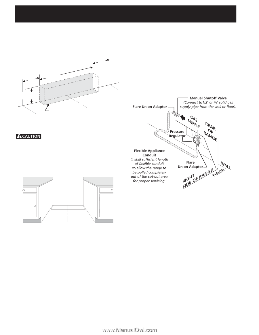
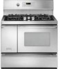
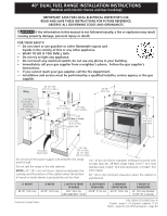
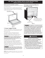
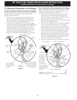
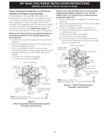
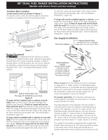
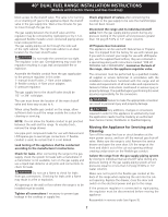
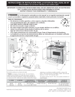
40" DUAL FUEL RANGE INSTALLATION INSTRUCTIONS (Models with Electric Ovens and Gas Cooktop) Junction Box Location Locate junction box as shown in Figure 7. If a service cord is used, the wall receptacle should be located in accordance with the dimensions below. Center Line of Range 10" (25.4 cm) 7" Max. (17.8 cm Max.) 20" (50.8 cm) 10" (25.4 cm) WALL FLOOR Locate Electrical Hook-up Inside Shaded Area Center Line of Range Figure 7 Range Placement To eliminate the risk of burns or fire by reaching over heated surface units, cabinet storage space located above the range should be avoided. If cabinet storage space is to be provided, the risk can be reduced by installing a range hood that projects horizontally a minimum of 5" (12.7 cm) beyond the bottom of the cabinet. on the floor where the back edge of the range will be. Now install anti-tip brackets (see "Anti-Tip Brackets Installation", page 10). If range will not be installed against a cabinet, move range into final position. Mark on the floor along both sides of the range. If back of range will not be flush with the wall (the location of the outlet may not allow the range to be positioned against the wall), draw a line on the floor where the back edge of the range will be. Now install anti-tip brackets (see "Anti-Tip Brackets Installation", page 10). Gas Supply Installation Center Line of Range Follow instructions for the type of installation you have Figure 8 If range will be installed with a cabinet on both sides, draw a center line on the floor between the cabinets (see figure 8). If back of range will not be flush with the wall (the location of the outlet may not allow the range to be positioned against the wall), draw a line on the floor where the back edge of the range will be. Now install anti-tip brackets (see "Anti-Tip Bracket Installation, page 10). If range will be installed with a cabinet on one side only, move the range into final position. Draw a line on the floor along the side of the range that is not against the cabinet. If back of range will not be flush with the wall (the location of the outlet may not allow the range to be positioned against the wall), draw a line Figure 9 When shipped from the factory, this unit is designed to operate on 4" water column (1.0 kPa) Natural gas manifold pressure. A convertible pressure regulator (see figure 2) is connected to the range manifold and MUST be connected in series with the gas supply line. To access the regulator, remove the drawer. For proper operation, the maximum inlet pressure to the regulator should be no more than 14" of water column pressure (3.5 kPa). The inlet pressure to the regulator must be at least 1" (.25 kPa) greater than the regulator manifold pressure setting. The regulator is set for 4" water column (1.0 kPa) Natural gas manifold pressure; the inlet pressure must be at least 5" water column (1.25 kPa) Natural gas. For LP/Propane gas, the regulator must be set for 10" water column (2.5 kPa) manifold pressure; the inlet pressure must be at least 11" water column (2.75 kPa). The supply line should be equipped with an approved shutoff valve (see Figure 9). This valve should be located in the same room as the range and should be in a location that allows ease of opening and closing. Do not 6
-
 1
1 -
 2
2 -
 3
3 -
 4
4 -
 5
5 -
 6
6 -
 7
7 -
 8
8 -
 9
9 -
 10
10 -
 11
11 -
 12
12 -
13
-
14
-
15
-
16
-
17
-
18
-
19
-
20
-
21
-
22
-
23
-
24
 |
 |