Frigidaire FPEF3077QF Installation Instructions
Frigidaire FPEF3077QF Manual
 |
View all Frigidaire FPEF3077QF manuals
Add to My Manuals
Save this manual to your list of manuals |
Frigidaire FPEF3077QF manual content summary:
- Frigidaire FPEF3077QF | Installation Instructions - Page 1
30" (762 mm) ELECTRIC RANGE INSTALLATION INSTRUCTIONS (For 4 Wire, 60 Hz. Systems) INSTALLATION AND SERVICE MUST BE PERFORMED BY A QUALIFIED INSTALLER. IMPORTANT: SAVE FOR LOCAL ELECTRICAL INSPECTOR'S USE. READ AND SAVE THESE INSTRUCTIONS FOR FUTURE REFERENCE. Clearances and Dimensions 1. Provide - Frigidaire FPEF3077QF | Installation Instructions - Page 2
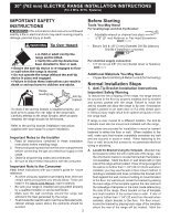
30" (762 mm) ELECTRIC RANGE INSTALLATION INSTRUCTIONS (For 4 Wire, 60 Hz. Systems) IMPORTANT SAFETY INSTRUCTIONS If the information in this manual is not followed exactly, a fire or electrical shock may result causing property damage, personal injury or death. Before Starting Tools You May Need - Frigidaire FPEF3077QF | Installation Instructions - Page 3
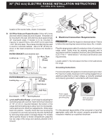
outlet 6" (152 mm) above the floor in the wall behind the range. Grounding Instructions For personal safety, this appliance must be properly grounded. For maximum safety, the power cord must be plugged into an electrical outlet that is correct voltage, is correctly polarized and properly grounded in - Frigidaire FPEF3077QF | Installation Instructions - Page 4
Reinstall in reverse order making sure to level the range and check electrical connections. See pages 2 and 3 for proper anchoring instructions. Before You Call for Service Read the "Before You Call" and operating instruction sections in your Use & Care Manual. It may save you time and expense. The - Frigidaire FPEF3077QF | Installation Instructions - Page 5
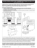
PAR L'INSPECTEUR EN ÉLECTRICITÉ. LISEZ ET CONSERVEZ CES INSTRUCTIONS POUR CONSULTATION FUTURE. Dimensions et espaces libres 1. ées doivent être appliquées. Les distances données sont minimales. La surface de support doit être solide et au niveau. VUE DE FACE PROFIL Espace minimum aux côtés de - Frigidaire FPEF3077QF | Installation Instructions - Page 6
instructions au consommateur. Note importante au consommateur Conservez ces instructions avec votre guide terre par un installateur ou un technicien de service qualifié. • Assurez-vous que les revê tapes normales d'installation 1. Instructions de montage du support de contrerenversement La cuisinière - Frigidaire FPEF3077QF | Installation Instructions - Page 7
riaux en béton. Utilisez un serre écrou ou un tournevis plat afin de fixer le support en place. (32 mm) 11/16" (17 mm) Côté de la cuisinière 152 mm (6") au-dessus du plancher dans le mur derrière le fourneau. Instructions de mise à la terre Pour des raisons de sécurité personnelle, cet appareil - Frigidaire FPEF3077QF | Installation Instructions - Page 8
vérifiez les raccordements électriques. Voyez les pages 2 et 3 pour les instructions correctes d'ancrage. Avant que vous ne fassiez un appel de service Lisez "Avant d'appeler" et les sections de notices d'opération de votre Guide d'utilisation et d'entretien, ils peuvent vous sauver temps et argent
-
 1
1 -
 2
2 -
 3
3 -
 4
4 -
 5
5 -
 6
6 -
 7
7 -
8
 |
 |
1
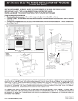
30" (762 mm) ELECTRIC RANGE INSTALLATION INSTRUCTIONS
(For 4 Wire, 60 Hz. Systems)
INSTALLATION AND SERVICE MUST BE PERFORMED BY A QUALIFIED INSTALLER.
IMPORTANT: SAVE FOR LOCAL ELECTRICAL INSPECTOR'S USE.
READ AND SAVE THESE INSTRUCTIONS FOR FUTURE REFERENCE.
P/N
316259203 REV C (1409)
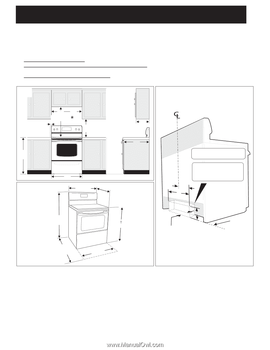
Clearances and Dimensions
1.
Provide adequate clearances between the range and adjacent combustible surfaces.
2.
Location—Check location where the range will be installed. Check for proper electrical supply, and the stability
of the floor.
3.
Dimensions that are shown must be used. Given dimensions provide minimum clearance. Contact surface must
be solid and level.
*30" (762 mm) MINIMUM CLEARANCE BETWEEN THE TOP OF THE COOKING SURFACE AND THE
BOTTOM OF AN UNPROTECTED
WOOD OR METAL CABINET; OR 24" (610 mm) MINIMUM WHEN BOTTOM OF WOOD OR METAL CABINET IS PROTECTED BY NOT
LESS THAN 1/4" (6 mm) FLAME RETARDANT MILLBOARD COVERED WITH NOT LESS THAN NO. 28 MSG SHEET STEEL, 0.015"
(0.4 mm) STAINLESS STEEL, 0.024" (0.6 mm) ALUMINUM OR 0.020" (0.5 mm) COPPER. 0" (0 mm) CLEARANCE IS THE MINIMUM FOR
THE REAR OF THE RANGE. FOLLOW ALL DIMENSION REQUIREMENTS PROVIDED ABOVE TO PREVENT PROPERTY DAMAGE,
POTENTIAL FIRE HAZARD, AND INCORRECT COUNTERTOP AND CABINET CUTS.
TO ELIMINATE THE RISK OF BURNS OR FIRE BY REACHING OVER HEATED SURFACE UNITS, CABINET STORAGE SPACE
LOCATED ABOVE THE SURFACE UNITS SHOULD BE AVOIDED. IF CABINET STORAGE IS TO BE PROVIDED, THE RISK CAN
BE REDUCED BY INSTALLING A RANGE HOOD THAT PROJECTS HORIZONTALLY A MINIMUM OF 5" (127 mm) BEYOND THE
BOTTOM OF THE CABINETS.
English - Pages 1-4
Français - Pages 5-8
FRONT
VIEW
Minimum to wall
on either side of
range above
36’’ (914 mm)
height.
SIDE
VIEW
1”
(25 mm)
36”
(914 mm)
30”
(762 mm)
Minimum
30”
(762 mm)
18”
(457 mm)
Minimum to
cabinets on
either side of
range.
13”
330 mm
Maximum depth
for cabinets
above range top.
0” (0 mm) clearance below cooking top and at rear of range.
30”
(762 mm)
RANGE
OVERALL
DIMENSIONS
30”
(762 mm)
25- 3/4”
(654 mm)
48”
(1219 mm)
Maximum
49”
(1245 mm)
Maximum
Door Open
29- 7/8”
(759 mm)
36
1/8”
Centerline of
range
All dimensions for electrical outlet location
are maximum.
Dashed cubed area
shows where the electrical outlet must be
installed
for flush to the wall installation.
25”
635 mm
11”
(279 mm)
22”
(559 mm)
Wall
Edge
2-5/8” (67 mm) for models
equipped with warmer drawers
3-1/2” (89 mm) for models
equipped with storage drawers
6”
(152 mm)
(3 mm)
(940 mm)