Frigidaire GLEH1642FS Wiring Diagram (All Languages)
Frigidaire GLEH1642FS - 3.1 cu. Ft. Laundry Center Manual
 |
UPC - 012505376368
View all Frigidaire GLEH1642FS manuals
Add to My Manuals
Save this manual to your list of manuals |
Frigidaire GLEH1642FS manual content summary:
- Frigidaire GLEH1642FS | Wiring Diagram (All Languages) - Page 1
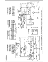
THIS APPLIANCE CAPABLE OF CONDUCTING ELECTRICAL CURRENT ARE GROUNDED. IF GROUNDING WIRES, SCREWS, STRAPS, NUTS OR WASHERS USED TO COMPLETE A PATH TO GROUND ARE REMOVED FOR SERVICE, THEY MUST BE RETURNED TO THEIR ORIGINAL POSITION AND PROPERLY FASTENED. OPERATION - DRYER On electric model dryers, air - Frigidaire GLEH1642FS | Wiring Diagram (All Languages) - Page 2
- Frigidaire GLEH1642FS | Wiring Diagram (All Languages) - Page 3
- Frigidaire GLEH1642FS | Wiring Diagram (All Languages) - Page 4
-
 1
1 -
 2
2 -
 3
3 -
 4
4
 |
 |
CAUTION:
TO SERVICE MACHINE, POWER MUST BE DISCONNECTED!
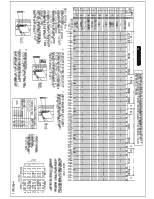
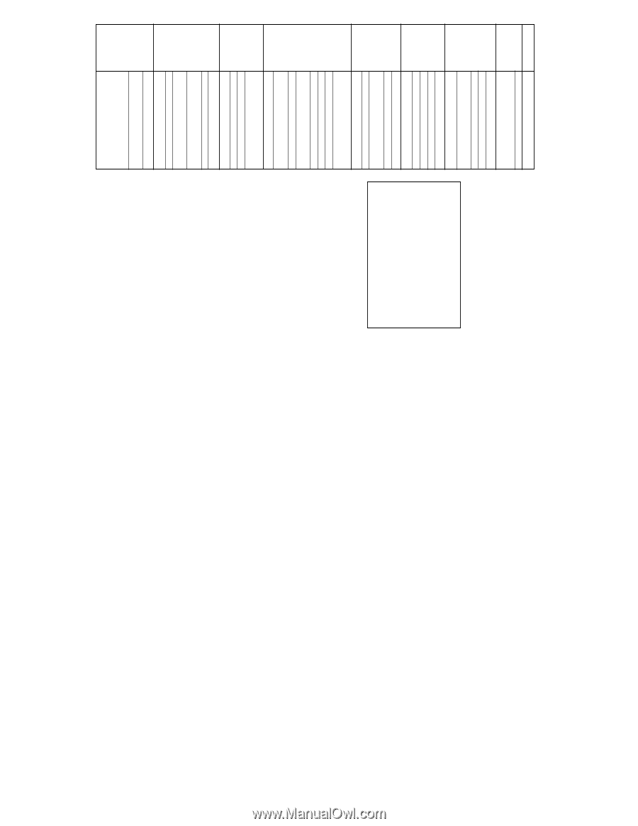
DRYER TROUBLESHOOTING
PROBLEM
Motor runs but
drum does not
operate
Drum operates
but is noisy
Motor will not
stop
Motor does not
start
Slow drying-
improper drying
Clothes not
drying on auto-
dry setting
Drum turns but
heat does not
come on
Element burns
out frequently
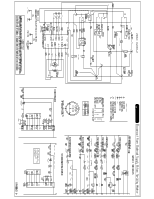
RESISTORS
The resistor, located in the thermostat heater circuit,
causes the thermostat heater to generate varying
amounts of heat. Resistors are connected to the
timer or selector switches. Refer to the applicable
wiring diagram.
Resistors are checked with an ohm meter and
resistor values are marked on the schematic wiring
diagram. A bad resistor will give improper drying
temperatures.
CONTROL THERMOSTAT
The thermostat and bias heater are located on the
blower housing.
CHECKING THE CONTROL
THERMOSTAT
Remove harness wires from the thermostat.
Determine the interior wiring by referring to the wiring
diagram. Use an ohm meter to check the
thermostats.
1.
Remove the exhaust venting from the rear of
dryer. Place a thermometer (pocket type
reading at least 300° F.) in rear of exhaust pipe.
If dryer is installed between cabinets, making
rear access difficult, the temperature can be
checked by placing a thermocouple in the lint
trap opening. Thermocouple shall be located
one inch to the right of lint screen opening center
line and extend three inches below the top of
opening.
2.
Set timer for 30 minutes, or long enough to
permit cycling of thermostat.
3.
Allow thermostat to cycle 3 or 4 times.
4.
Check temperature immediately after the third
or fourth cycle of thermostat. The temperatures
(depending on the temperature setting) should
conform to those listed in the Temperature
Chart.
-
AT EXHAUST DUCT
-
NO LOAD
OR LINT TRAP
TRIP TEMP
SETTING
HIGH
145-190° F.
MEDIUM
2-10° F. lower than high heat
LOW
2-10° F. lower than medium heat
NOTE:
LONG EXTENDED VENTS AFFECT DRUM
TEMPERATURES.
HI-LIMIT THERMOSTAT
The hi-limit thermostat, single-pole, single throw
switch wired in series with the control thermostat
and heat source, is mounted to the top of the heater
housing.
Should the control thermostat fail or an
air blockage occur, raising the heater housing
temperature to 260° F. on electric or 240° F. on
gas., the hi-limit thermostat opens the circuit to
the heat source and allows the heater housing to
cool down to 190° F.
To check the thermostat, remove drum. To check
for stuck contacts in the thermostat, start the dryer
and run on HIGH heat
with the exhaust duct
completely blocked
. The hi-limit thermostat MUST
open within three minutes.
To check for an open thermostat, remove the
harness wires from the thermostat terminals. Test
for continuity. You should have continuity through a
good thermostat at room temperature.
SAFETY THERMOSTAT
The safety thermostat is wired in series with the
motor for ELECTRIC MODELS and the burner for
GAS MODELS. The purpose of the safety
thermostat is to shut down the dryer if the control
thermostat and hi-limit thermostat fail to open. Once
the safety thermostat has opened, it must be
replaced. The condition that caused it to open must
be corrected.
HEATER ASSEMBLY
(ELECTRIC ONLY)
The heater assembly (208/240 volts) is located
behind the drum. Perforations in the drum back allow
heated air to be drawn into the drum.
The heater is an open coil type heater made from a
continuous coil of resistance wire attached to a metal
support plate with ceramic stand offs.
Heater Assembly Testing:
1.
Disconnect Laundry Center from electrical
supply.
2.
Remove drum.
3.
Remove leads to the heater element.
4.
Connect ohmmeter across heater element
terminals.
5.
Check each terminal to ground.
6.
If open or grounded, replace heater element.
To Remove or Replace Heating Element:
1.
Disconnect Laundry Center from electrical
supply.
2.
Remove drum.
3.
Disconnect wires from safety thermostat, hi-
limit thermostat, and ceramic insulator.
4.
Remove four screws securing heating element
assembly to rear panel and remove assembly.
5.
Install new heating element.
6.
Reverse procedure to reassemble.
IGNITOR
T
he ignitor is a silicon thermistor.
When it attains
approximately 1800 F, the sensor (mounted on the
side of the burner tube) detectes this high radiant
heat and opens its contacts.
This energizes the secondary solenoid valve coil,
allowing gas to flow through the gas valve orifice
and impinge upon the hot glowing ignitor.
The total
sequence occurs within
15 to 90 seconds.
The igniter is mounted to the
burner at an angle with the silicon carbide stem
extended into the flame area.
The stem is very fragile
and susceptible to contamination from skin oils.
HANDLE WITH CARE
by using the ignitor's insulated
support.
To test the ignitor:
1.
Disconnect Laundry Center from electrical supply.
2. Remove the dryer access panel and safety cover.
3.
Disconnect plug connector from ignitor-to-coil
harness.
4. Check resistance value of ignitor.
It should be
approximately 50 to 800 Ohms depending on the
room temperature.
To replace ignitor:
1.
Disconnect Laundry Center from electrical supply.
2. Remove burner assembly.
3.
Remove burner tube from burner assembly.
4. Remove the 1/4" hex head screw and washer
securing ignitor to its mounting bracket.
5.
Reverse procedure to reinstall.
DOOR SWITCH
Whenever the door is opened, the door switch will
open the circuit to the motor and the external switch
in the motor will open the circuit to the heat source.
CHECKING THE MOTOR
The drive motor is 1/4 H.P., 1725 RPM with
automatic reset overload protector.
1. Disconnect electrical current and remove
ventilation panel. Remove harness wires from
motor.
2. Operate motor by connecting a properly fused
service cord to terminals 4 and 5. The motor
should start and run.
3.
If motor runs, problem is open circuits in the dryer
electrical or control system. If motor does not
run, check the centrifugal switch.
4.
When motor runs and the problem is NO HEAT,
check continuity between terminals 1 and 2 with
the switch button out (run position).
No continuity shows the switch is inoperative.
Replace motor.
DRYER DRIVE BELT
To Remove or Replace Dryer Drive Belt:
1.
Disconnect Laundry Center from electrical supply.
2. Remove front panel and air duct assembly.
3.
Disconnect belt from idler pulley and motor pulley.
4.
Remove belt from dryer drum.
5. Install new belt.
6.
Reverse procedure to reassemble.
WHAT TO LOOK FOR
Broken or loose belt
Loose motor, idler pulley, or
spring
Drum out of shape
Worn idler pulley
Belt squeaking or frayed
Motor (bearing), motor pulley
loose, blower
Drum seals worn
Incorrect wiring
Grounded motor or wiring
Grounded heat element
Faulty timer
Open timer resistor
Blown fuse
Timer or motor inoperative
Housing wiring not properly
connected to dryer
Inoperative door switch
Faulty “Push to Start” switch
Blocked or plugged lint collector,
blower housing or vent pipe
Vent pipe too long
Clothes too wet when put in dryer
Dryer is overloaded
Drum set is worn or out of
position
Door gasket not sealing correctly
Control or safety thermostats
inoperative
House voltage fluctuating or low
Customer selected wrong timer
setting
Inoperative resistor
Inoperative control thermostat
Inoperative heating element
Inoperative heating element
Inoperative timer
Loose terminals-tighten
connections
Inoperative control or safety
thermostat
Inoperative motor switch
Broken wire in wiring harness
Worn drum seals. Replace
Connections not tight at element
terminals
Reduced air flow. Check for
proper installation &
maintenance of duct work. (See
Installation Instructions)
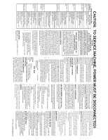
CAUTION
THIS MACHINE MUST BE
ELECTRICALLY GROUNDED
It can be grounded thru the ground lead in the
4-prong power cord, if plugged into a properly
grounded appliance outlet or thru a separate
No. 12 or larger wire from the cabinet to an
established ground. In all cases, the grounding
method must comply with any local electrical
code requirements.
IMPORTANT - RECONNECT ALL
GROUNDING DEVICES
ALL PARTS OF THIS APPLIANCE CAPABLE
OF CONDUCTING ELECTRICAL CURRENT
ARE GROUNDED. IF GROUNDING WIRES,
SCREWS, STRAPS, NUTS OR WASHERS
USED TO COMPLETE A PATH TO GROUND
ARE REMOVED FOR SERVICE, THEY MUST
BE RETURNED TO THEIR ORIGINAL
POSITION AND PROPERLY FASTENED.
OPERATION - DRYER
On electric model dryers, air is drawn into the heater
housing and across the open coils of the electric
heater. On gas model dryers, air is drawn into the
combustion chamber and over the burner flame.
It
then is drawn through the tumbling clothes, picking
up moisture and lint. Lint is filtered out as the air
passes from the drum into the blower where it is
discharged out the vent. The air temperature is
controlled by the biased thermostat according to
the setting of the fabric selector switch. The length
of the drying cycle is controlled by the number of
minutes selected on the timer, or automatically
controlled by the timer, in conjunction with the
electronic moisture sensor, for the type of fabric
selected (automatic dry cycle).
To operate the dryer, first check the lint screen and
be certain that the screen is completely free of all
lint. Place clothes in dryer and close door. (Dryer
will not operate unless door is closed.)
1.
Select the drying time, or automatic drying
cycle, by turning timer knob to the right.
2.
Set drying temperature using timer for the type
of fabric being dried.
3.
To start the dryer, turn the start knob to the
right and hold for 2 seconds.
DRUM SPEED
48-54 RPM in a counterclockwise direction as
viewed from the front.
PART NO. 134969500B (0810)