Frigidaire PLMVZ169HC Installation Instructions
Frigidaire PLMVZ169HC - 1.6 cu. Ft. Microwave Oven Manual
 |
UPC - 012505559518
View all Frigidaire PLMVZ169HC manuals
Add to My Manuals
Save this manual to your list of manuals |
Frigidaire PLMVZ169HC manual content summary:
- Frigidaire PLMVZ169HC | Installation Instructions - Page 1
• If a new electrical outlet is required, its installation should be completed by a qualified electrician before the Microwave Oven is installed. See 3 ELECTRICAL GROUNDING INSTRUCTIONS on page 2. 1 MOUNTING SPACE This Microwave Oven/Hood requires a mounting space on a wall as shown in Figure 1. It - Frigidaire PLMVZ169HC | Installation Instructions - Page 2
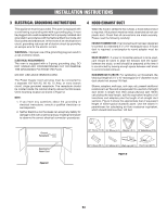
the Microwave Oven mounting location as shown in Figure 2. NOTE: 1. If you have any questions about the grounding or electrical instructions, 3 shows the approximate feet of equivalent length of some typical ductwork parts. Use the values in parentheses for calculating air flow resistance equivalent - Frigidaire PLMVZ169HC | Installation Instructions - Page 3
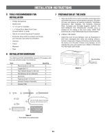
carton, bend the carton flaps back and tilt the oven over to rest on plastic foam pad. Lift carton off oven and remove all packing materials, Installation Instructions, Wall Template, Top Template, Charcoal Filter, Turntable and Turntable Support; however, DO NOT REMOVE THE WAVEGUIDE COVER, which is - Frigidaire PLMVZ169HC | Installation Instructions - Page 4
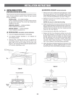
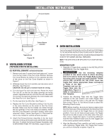
INSTALLATION INSTRUCTIONS 8 VENTILATION SYSTEM (PREPARING OVEN FOR INSTALLATION) This microwave oven/hood is designed for adaptation to three types of hood ventilation systems. Select the type required for your installation. RECIRCULATING - non-vented, ductless. Follow installation procedure (A). - Frigidaire PLMVZ169HC | Installation Instructions - Page 5
fan cover bracket on the top of the outercase cabinet after mounting the oven. To attach the Exhaust Damper Assembly, refer to MOUNTING OVEN TO THE WALL, page 6 Figure 17. Figure 11 9 OVEN INSTALLATION THIS OVEN CANNOT BE PROPERLY INSTALLED WITHOUT REFERRING TO THE MOUNTING INSTRUCTIONS FOUND ON - Frigidaire PLMVZ169HC | Installation Instructions - Page 6
INSTALLATION INSTRUCTIONS 9 OVEN INSTALLATION cont. Toggle Bolt Toggle Nut Mounting Plate Figure 12 Space more than wall thickness Wall Figure 13 Figure 14 MOUNTING OVEN TO THE WALL Two people are recommended to attach the Microwave Oven/ Hood to the Mounting Plate. 1. Thread the power - Frigidaire PLMVZ169HC | Installation Instructions - Page 7
INSTALLATION INSTRUCTIONS CHECKLIST FOR INSTALLATION 1. Make sure the unit has been installed according to all of the Installation Instructions and the Wall and Top Cabinet Templates. 2. Plug in the power cord. 3. Keep the Operation Manual. E7 - Frigidaire PLMVZ169HC | Installation Instructions - Page 8
NOTES E8 - Frigidaire PLMVZ169HC | Installation Instructions - Page 9
y cuidadosamente. • IMPORTANTE Guarde estas instrucciones para uso por parte del inspector local. • IMPORTANTE Cumpla todos los códigos y todas las instrucciones antes de instalar el horno microondas "Over the Range". Se recomiendan dos personas para instalar este producto. • NOTA PARA - Frigidaire PLMVZ169HC | Installation Instructions - Page 10
las transiciones y adaptadores más la longitud de todas las secciones rectas de ducto. La Figura 3 muestra la longitud equivalente aproximada en pies de algunas partes de ducto típicas. Utilice los valores dentro de paréntesis para calcular la resistencia al flujo de aire equivalente que debe ser un - Frigidaire PLMVZ169HC | Installation Instructions - Page 11
30 mm Anillo de Refuerzo Tornillo Auto-Perforante de 4 x 8 mm Regulador de Succión de Extracción Filtros de grasa Cantidad 6 4 2 2 1 4 1 2 7 PREPARACIÓN DEL HORNO 1. Abra la parte inferior de la caja de cartón, doble hacia atrás las alas de la caja de cartón y voltee la caja para colocar el horno - Frigidaire PLMVZ169HC | Installation Instructions - Page 12
Unidad de Ventilador de la Campana Extractora ahora está girada para operación de escape horizontal. 6. Sujete el Regulador de Succión de Extracción a la parte trasera de la Placa de Montaje deslizándolo dentro de las ranuras. Véase la Figura 10. Utilice dos Tornillo Autoperforante de 4 x 8 de los - Frigidaire PLMVZ169HC | Installation Instructions - Page 13
DE INSTALACIÓN Cubierta del Ventilador 6. Después de montar el horno, sujete el Regulador de Succión de Extracción a la cubierta del ventilador ubicada en la parte superior del horno. Para sujetar el Regulador de Succión de Extracción, remítase al capítulo "MONTAJE DEL HORNO EN LA PARED", página - Frigidaire PLMVZ169HC | Installation Instructions - Page 14
à micro-ondes et sa hotte sur la plaque de fixation. 1. Passez le cordon secteur par le trou fait dans le fond du cofret supérieur. 2. Instale el horno inclinándolo adelante y resbalándolo sobre las lengüetas de la Placa de Montaje. Gire el horno arriba tan descansa contra la pared - Frigidaire PLMVZ169HC | Installation Instructions - Page 15
instalada de acuerdo con todas las Instrucciones de Instalación y las Plantillas de Pared y las Plantillas del Gabinete Superior. 2. Enchufe el cable de energía. 3. Guarde el Manual de Operación. S7 - Frigidaire PLMVZ169HC | Installation Instructions - Page 16
NOTAS S8 - Frigidaire PLMVZ169HC | Installation Instructions - Page 17
appareil. • Faites appel à un électricien de métier s'il faut d'abord installer une nouvelle prise de courant pour le four à microondes à hotte intégrée. Voir paragraphe 3 INSTRUCTIONS DE MISE À LA TERRE à la page 2. 1 L'ESPACE DE SUPPORT La Schéma 1 vous montre l'espace de montage nécessaire à ce - Frigidaire PLMVZ169HC | Installation Instructions - Page 18
INSTRUCTIONS D'INSTALLATION 3 INSTRUCTIONS DE MISE À LA TERRE Cet appareil doit être mis à la terre. Ce four est équipé d'un cordon d'alimentation avec fil de mise à la terre, et d'une fiche de mise à la terre. Il faut le brancher dans une prise murale qui a été installée correctement et mise à la - Frigidaire PLMVZ169HC | Installation Instructions - Page 19
instructions d'installation, le gabarit mural, le gabarit de plafond, le filtre à charbon, le plateau tournant et son support. Cependant N'ENLEVEZ PAS LE CACHE DU GUIDE faites pas fonctionner le four et contactez votre revendeur ou UN SERVICE AGRÉÉ DE DÉPANNAGE ELECTROLUX. Schéma 5 Plaque de fi - Frigidaire PLMVZ169HC | Installation Instructions - Page 20
INSTRUCTIONS D'INSTALLATION 8 SYSTÈME DE VENTILATION (PRÉPARANT LE FOUR POUR L'INSTALLATION) Le four à micro-ondes à hotte intégrée est conçu pour s'adapter à trois types de systèmes de ventilation par hotte. Choisissez le type nécessaire pour votre installation entre le support interne et le - Frigidaire PLMVZ169HC | Installation Instructions - Page 21
le four. Faites attention de ne pas pincer le fil de connexion entre le support interne et le ventilateur de hotte. Voir Schéma 11. 4. Placez le carter avant de F5 CE FOUR NE PEUT ÊTRE INSTALLÉ CONVENABLEMENT QUE SI L'ON SE RÉFÈRE AUX INSTRUCTIONS DE MONTAGE QUI SE TROUVENT SUR LES DEUX GABARITS. - Frigidaire PLMVZ169HC | Installation Instructions - Page 22
INSTRUCTIONS D'INSTALLATION 9 INSTALLATION DE FOUR suite 4. Alignez soigneusement la plaque de plaque de fixation en vous servant de deux vis autotaradeuses 4 x 8 mm dans les PIÈCES D'INSTALLATION. Consultez la Figure 16. Schéma 15 Ailettes Boulon Plaque de fixation Schéma 12 Espace supérieur - Frigidaire PLMVZ169HC | Installation Instructions - Page 23
INSTRUCTIONS D'INSTALLATION PENSE-BÊTE POUR L'INSTALLATION 1. Assurez-vous que l'appareil a été installé en suivant toutes les instructions et en utilisant le gabarit mural et de plafond. 2. Branchez le cordon d'alimentation secteur. 3. Conservez le mode d'emploi. F7 - Frigidaire PLMVZ169HC | Installation Instructions - Page 24
REMARQUES F8
-
 1
1 -
 2
2 -
 3
3 -
 4
4 -
 5
5 -
 6
6 -
 7
7 -
8
-
9
-
10
-
11
-
12
-
13
-
14
-
15
-
16
-
17
-
18
-
19
-
20
-
21
-
22
-
23
-
24
 |
 |

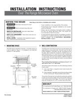
1 MOUNTING SPACE
This Microwave Oven/Hood requires a mounting space on
a wall as shown in Figure 1. It is designed to be used with
standard 12" wall cabinets.
TINSEB151WRRZ
Printed in Thailand
Backsplash
Figure 1
15.5"
30" or more
from cooking
surface
30"
At least 2"
12"
P/N 316137234
NEED HELP?
For customers in the United States, call: 1-800-944-9044
For customers in Canada, call: 1-800-213-9397 (English)
1-800-668-4606 ext.8199 (French)
READ CAREFULLY. KEEP THESE INSTRUCTIONS.
BEFORE YOU BEGIN
•
IMPORTANT
Save these instructions for local
inspector’s use.
•
IMPORTANT
Observe all governing codes and
coordinates.
•
NOTE TO INSTALLER
– Be sure to leave these
instructions with the Consumer.
•
NOTE TO CONSUMER
– Keep these instructions for
future reference.
•
SKILL LEVEL
– Installation of this appliance requires
basic mechanical and electrical skills.
•
Proper installation is the responsibility of the installer.
•
Product failure due to improper installation is not covered
under the Warranty.
•
Please read all instructions thoroughly before installing
the Over the Range Microwave Oven. Two people are
recommended to install this product.
•
If a new electrical outlet is required, its installation should be
completed by a quali
fi
ed electrician before the Microwave
Oven is installed. See
3 ELECTRICAL GROUNDING
INSTRUCTIONS
on page 2.
Read these instructions completely and carefully.
INSTALLATION
INSTRUCTIONS
Over The Range Microwave Oven
2 WALL CONSTRUCTION
This Microwave Oven/Hood should be mounted against and
supported by a
fl
at vertical wall. The wall must be
fl
at for
proper installation. If the wall is not
fl
at, use spacers to
fi
ll in
the gaps. Wall construction should be a minimum of 2" x 4"
wood studding and
³⁄₈
" or more thick dry wall or plaster/lath.
The mounting surfaces must be capable of supporting weight
of 110 pounds—the oven and contents—AND the weight of
all items which would normally be stored in the top cabinet
above the unit.
The unit should be attached to a minimum of one 2" x 4"
wall stud or two 2" x 3" wall studs.
To
fi
nd the location of the studs, one of the following methods
may be used:
A. Use a stud finder, a magnetic device which locates the
nails in the stud.
B. Use a hammer to tap lightly across the mounting surface
to find a solid sound. This will indicate stud location.
The center of the stud can be located by probing the wall with
a small nail to
fi
nd the edges of the stud and then placing a
mark halfway between the edges. The center of any adjacent
studs will normally be 16" or 24" to either side of this mark.
66" or more
from floor