Fujitsu MHW2080AT Manual/User Guide
Fujitsu MHW2080AT - Mobile 80 GB Hard Drive Manual
 |
View all Fujitsu MHW2080AT manuals
Add to My Manuals
Save this manual to your list of manuals |
Fujitsu MHW2080AT manual content summary:
- Fujitsu MHW2080AT | Manual/User Guide - Page 1
3.2 Mounting 3.3 Cable Connections 3.4 Jumper Settings This chapter gives the external dimensions, installation conditions, surface temperature conditions, cable connections, and switch settings of the hard disk drives. For information about handling this hard disk drive and the system installation - Fujitsu MHW2080AT | Manual/User Guide - Page 2
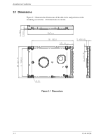
Installation Conditions 3.1 Dimensions Figure 3.1 illustrates the dimensions of the disk drive and positions of the mounting screw holes. All dimensions are in mm. Figure 3.1 Dimensions 3-2 C141-E250 - Fujitsu MHW2080AT | Manual/User Guide - Page 3
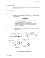
3.2 Mounting 3.2 Mounting For information on mounting, see the "FUJITSU 2.5-INCH HDD INTEGRATION GUIDANCE (C141-E144)." (1) Orientation The disk drives can be mounted in any direction. (2) Frame The MR head bias of the HDD disk enclosure (DE) is zero. The mounting frame is connected to SG. Use - Fujitsu MHW2080AT | Manual/User Guide - Page 4
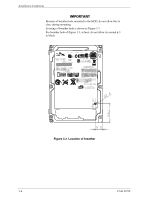
Installation Conditions Because of breather hole mounted to the HDD, do not allow this to close during mounting. Locating of breather hole is shown as Figure 3.3. For breather hole of Figure 3.3, at least, do not allow its around φ 3 to block. Figure 3.3 Location of breather 3-4 C141-E250 - Fujitsu MHW2080AT | Manual/User Guide - Page 5
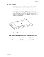
mounted in a cabinet refer to the ambient temperature at a point 3 cm from the disk drive. The ambient temperature must satisfy the temperature conditions described in Section 1.4, and the airflow must be considered to prevent the DE surface temperature from exceeding - Fujitsu MHW2080AT | Manual/User Guide - Page 6
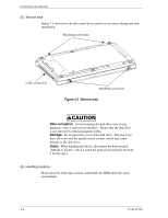
screw hole Figure 3.5 Service area Data corruption: Avoid mounting the disk drive near strong magnetic sources such as loud speakers. Ensure that the disk drive is not affected by external magnetic fields. Damage: Do not press the cover of the disk drive. Pressing it too hard, the cover and the - Fujitsu MHW2080AT | Manual/User Guide - Page 7
impact when you use an electric driver. HDD is occasionally damaged by the impact of the driver. (2) Please observe the tightening torque of the screw strictly. M3 0.49N•m (5 kgf•cm). - Recommended equipments ESD Shock Contents Wrist strap ESD mat Low shock driver Model JX-1200-3056-8 SKY-8A - Fujitsu MHW2080AT | Manual/User Guide - Page 8
Installation Conditions 3.3 Cable Connections 3.3.1 Device connector The disk drive has the connectors and terminals listed below for connecting external devices. Figure 3.7 shows the locations of these connectors and terminals. Connector, setting pins PCA Figure 3.7 - Fujitsu MHW2080AT | Manual/User Guide - Page 9
for the cable connectors. Table 3.2 Cable connector specifications ATA interface and power supply cable (44-pin type) Name Cable socket (44-pin type) Model 89361-144 Manufacturer FCI For the host interface cable, use a ribbon cable. A twisted cable or a cable with wires that have - Fujitsu MHW2080AT | Manual/User Guide - Page 10
shows the pin assignment of the power supply connector (CN1). Figure 3.9 Power supply connector pins (CN1) 3.4 Jumper Settings 3.4.1 Location of setting jumpers Figure 3.10 shows the location of the jumpers to select drive configuration and functions. Figure 3.10 Jumper location 3-10 C141-E250 - Fujitsu MHW2080AT | Manual/User Guide - Page 11
3.11 Factory default setting 3.4.3 Master drive-slave drive setting Master drive (disk drive #0) or slave drive (disk drive #1) is selected. Open 1 CA 2 DB Open (a) Master drive 1 CA Open Short 2 DB (b) Slave drive Figure 3.12 Jumper setting of master or slave drive Note: Pins A and - Fujitsu MHW2080AT | Manual/User Guide - Page 12
on setting between pins Band D. Figure 3.13 CSEL setting Figure 3.14 and 3.15 show examples of cable selection using unique interface cables. By connecting the CSEL of the master drive to the CSEL Line (conducer) of the cable and connecting it to ground further, the CSEL is set to low level - Fujitsu MHW2080AT | Manual/User Guide - Page 13
3.4 Jumper Settings drive Figure 3.15 Example (2) of cable select drive 3.4.5 Power up in standby setting When pin C is grounded, the drive does not spin up at power on. C141-E250 3-13 - Fujitsu MHW2080AT | Manual/User Guide - Page 14
This page is intentionally left blank.
-
 1
1 -
 2
2 -
 3
3 -
 4
4 -
 5
5 -
 6
6 -
 7
7 -
8
-
9
-
10
-
11
-
12
-
13
-
14
 |
 |

CHAPTER 3 Installation Conditions
3.1
Dimensions
3.2
Mounting
3.3
Cable Connections
3.4
Jumper Settings
This chapter gives the external dimensions, installation conditions, surface
temperature conditions, cable connections, and switch settings of the hard disk
drives.
For information about handling this hard disk drive and the system installation
procedure, refer to the following Integration Guide.
C141-E144
C141-E250
3-1