Garmin GAD 42 Maintenance Manual
Garmin GAD 42 Manual
 |
View all Garmin GAD 42 manuals
Add to My Manuals
Save this manual to your list of manuals |
Garmin GAD 42 manual content summary:
- Garmin GAD 42 | Maintenance Manual - Page 1
GAD 42 MAINTENANCE MANUAL GARMIN International, Inc. 1200 E. 151st Street Olathe, KS 66062 USA 190-00159-01, Revision A July 2001 - Garmin GAD 42 | Maintenance Manual - Page 2
E. 151st Street Olathe, KS 66062 USA Telephone: 913-397-8200 Dealer Line: 1-800-800-1420 Web Site Address: www.garmin.com RECORD OF REVISIONS REVISION A REVISION DATE 07/03/01 Description Initial Release ECO # ----- Insertion Date By GAD 42 MAINTENANCE MANUAL P/N 190-00159-01 Page 1 Rev. A - Garmin GAD 42 | Maintenance Manual - Page 3
of up to $1,000,000 under Section 2410 of the Export Administration Act of 1979. Include this notice with any reproduced portion of this document. GAD 42 MAINTENANCE MANUAL P/N 190-00159-01 Page 2 Rev. A - Garmin GAD 42 | Maintenance Manual - Page 4
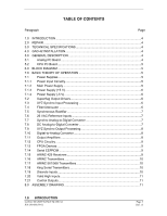
Paragraph Page 1.0 INTRODUCTION ...4 2.0 REPAIR ...4 3.0 TECHNICAL SPECIFICATIONS 4 4.0 GAD 42 INSTALLATION 4 5.0 GENERAL DESCRIPTION 4 5.1 Analog PC Board 4 5.2 CPU Outputs 11 8.0 ASSEMBLY DRAWING 11 1.0 INTRODUCTION GAD 42 MAINTENANCE MANUAL P/N 190-00159-01 Page 3 Rev. A - Garmin GAD 42 | Maintenance Manual - Page 5
service. 3.0 TECHNICAL SPECIFICATIONS Technical specifications for the GAD 42 are listed in the GAD 42 Installation Manual, P/N 190-00159-00. 4.0 GAD 42 INSTALLATION Installation information for the unit is found in the GAD 42 Installation Manual. 5.0 GENERAL DESCRIPTION The GAD 42 Interface Adapter - Garmin GAD 42 | Maintenance Manual - Page 6
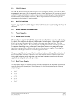
5.2 CPU PC Board The CPU PC Board contains the unit microprocessor and support circuitry, as well as two field programmable gate array (FPGA) integrated and producing the following output voltages: • +20 V • +12 V • -12 V • -20 V • +34 V GAD 42 MAINTENANCE MANUAL P/N 190-00159-01 Page 5 Rev. A - Garmin GAD 42 | Maintenance Manual - Page 7
diagram) are processed by identical circuitry, only the 11.8 Vac heading inputs, HEADING X and HEADING Y are discussed here. All Z synchro inputs are grounded in the GAD 42. GAD 42 MAINTENANCE MANUAL P/N 190-00159-01 Page 6 Rev. A - Garmin GAD 42 | Maintenance Manual - Page 8
PC board as previously described above for HEADING X and HEADING Y, and applied to one of two 4 channel, 12-bit A/D converters on the CPU PC Board. GAD 42 MAINTENANCE MANUAL P/N 190-00159-01 Page 7 Rev. A - Garmin GAD 42 | Maintenance Manual - Page 9
during certain operating conditions. The ROLL STEERING output amp is the same topology as described above, but uses lower power and lower gain push-pull output amps. This is possible due to higher impedance loads being driven by this output. GAD 42 MAINTENANCE MANUAL P/N 190-00159-01 Page 8 Rev - Garmin GAD 42 | Maintenance Manual - Page 10
contains unit software code, and can be erased and re-programmed by RS-232 interface when the GAD 42 is in test mode. The VPP program voltage for this device is provided by an 11.8 VDC be applied across a resistor, and out to FPGA "B" input. GAD 42 MAINTENANCE MANUAL P/N 190-00159-01 Page 9 Rev. A - Garmin GAD 42 | Maintenance Manual - Page 11
by the CPU. A diode provides transient voltage protection for the transistor. A capacitor and resistor form a low-pass filter to reduce highfrequency noise at the input. GAD 42 MAINTENANCE MANUAL P/N 190-00159-01 Page 10 Rev. A - Garmin GAD 42 | Maintenance Manual - Page 12
for over-current protection. A zener provides transient protection for the FET. 8.0 ASSEMBLY DRAWING Figure 2, page 13, shows an assembly drawing (with part numbers) for the GAD 42. GAD 42 MAINTENANCE MANUAL P/N 190-00159-01 Page 11 Rev. A - Garmin GAD 42 | Maintenance Manual - Page 13
OBI DRIVE COS NAV RMI DRIVE Y/OBI DRIVE SIN ROLL STEERING HI ROLL STEERING LO/GROUND MAIN RMI/OBI SUPERFLAG NAV RMI/OBI SUPERFLAG STEERING SUPERFLAG ARINC 561/568 SUPERFLAG DISCRETE OUTPUTS RS 232 SERIAL SYNC GAD 42 MAINTENANCE MANUAL P/N 190-00159-01 Figure 1. GAD 42 Block Diagram Page 12 Rev. A - Garmin GAD 42 | Maintenance Manual - Page 14
END PLATE 115-00265-00 SIDE EXTRUSION 135-00007-01 (2 PLCS) INSULATOR COVER 250-00064-00 (2 PLCS) BOARD HEADERS 334-00039-00 (3 PLCS) GAD 42 MAINTENANCE MANUAL P/N 190-00159-01 COVER 115-00266-00 INSULATOR COVER (2 PLCS) 250-00064-00 (REF) INSIDE SURFACE ONLY SCREW 211-632340-06 (4 PLCS) ANALOG
-
 1
1 -
 2
2 -
 3
3 -
 4
4 -
 5
5 -
 6
6 -
 7
7 -
8
-
9
-
10
-
11
-
12
-
13
-
14
 |
 |
GARMIN International, Inc.
1200 E. 151
st
Street
Olathe, KS
66062 USA
190-00159-01, Revision A
July 2001
GAD 42
MAINTENANCE MANUAL