Garmin GAD 43e Installation Manual
Garmin GAD 43e Manual
 |
View all Garmin GAD 43e manuals
Add to My Manuals
Save this manual to your list of manuals |
Garmin GAD 43e manual content summary:
- Garmin GAD 43e | Installation Manual - Page 1
GAD 43 Installation Manual 190-00899-00 May 2009 Rev. B - Garmin GAD 43e | Installation Manual - Page 2
- Garmin GAD 43e | Installation Manual - Page 3
guide, please e-mail: [email protected]. Garmin International, Inc. 1200 E. 151st Street Olathe, KS 66062 USA Telephone: 913-397-8200 Aviation Dealer Technical Support Line (Toll Free): (888) 606 5482 http://www.garmin.com Garmin GAD 43 Installation Manual 190-00899-00 Page A Rev. B - Garmin GAD 43e | Installation Manual - Page 4
Section 8 Appendix A Appendix B Appendix C Page Range i through vi 1-1 through 1-8 2-1 through 2-2 3-1 through 3-8 4-1 through 4-8 5-1 through 5-4 6-1 through 6-2 7-1 through 7-2 8-1 through 8-2 A-1 through A-2 B-1 through B-4 C-1 through C-8 Page B Rev. B GAD 43 Installation Manual 190-00899-00 - Garmin GAD 43e | Installation Manual - Page 5
required to be included on any and all reproductions in whole or in part of this manual. WARNING This product, its packaging, and its components contain chemicals known to the State of , please refer to our web site at www.garmin.com/prop65/. GAD 43 Installation Manual 190-00899-00 Page i Rev. B - Garmin GAD 43e | Installation Manual - Page 6
This Page Intentionally Left Blank Page ii Rev. B GAD 43 Installation Manual 190-00899-00 - Garmin GAD 43e | Installation Manual - Page 7
...4-1 4.1.1 P431 Connector...4-1 4.2 Functional Descriptions ...4-3 4.2.1 Power...4-3 4.2.2 Power Supply Outputs...4-3 4.2.3 Serial Data...4-3 4.2.4 Gyro Emulation Interfaces 4-4 4.2.5 Baro Correction Outputs ...4-6 4.2.6 Discretes...4-6 GAD 43 Installation Manual 190-00899-00 Page iii Rev. B - Garmin GAD 43e | Installation Manual - Page 8
Numbers...2-1 Table 2-2. Installation Accessories ...2-1 Table 3-1. Socket Contact Part Numbers 3-2 Table 3-2. Recommended Crimp Tools...3-2 Table 3-3. Backshell Assembly ...3-3 Table 4-1. P431 Connector Pin-Out...4-1 Table 5-1. Gyro Emulation Types...5-3 Page iv Rev. B GAD 43 Installation Manual - Garmin GAD 43e | Installation Manual - Page 9
most up-to-date bulletin and advisory information on the Garmin Dealer Resource web site at www.garmin.com using their Garmin-provided user name and password. MOD LEVEL SERVICE BULLETIN NUMBER SERVICE BULLETIN DATE PURPOSE OF MODIFICATION GAD 43 Installation Manual 190-00899-00 Page v Rev. B - Garmin GAD 43e | Installation Manual - Page 10
This page intentionally left blank Page vi Rev. B GAD 43 Installation Manual 190-00899-00 - Garmin GAD 43e | Installation Manual - Page 11
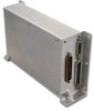
DESCRIPTION 1.1 Introduction The GAD 43 Adapter is an optional adapter for the G500/G600 Integrated Flight Decks that , the GAD 43 allows the existing ADI or attitude gyro to be removed when the G500/G600 system is installed. Figure 1-1. GAD 43 Unit View GAD 43 Installation Manual 190-00899 - Garmin GAD 43e | Installation Manual - Page 12
GAD 43 has one ARINC 429 input port to support input from the GRS 77 AHRS. 1.3.2 RS-232 Interface The GAD 43 has one RS-232 serial port to support communication with the GDU 620. 1.3.3 Analog Interfaces The GAD 43 the standard King altimeter. Page 1-2 Rev. B GAD 43 Installation Manual 190-00899-00 - Garmin GAD 43e | Installation Manual - Page 13
It is the responsibility of the installing agency to obtain the latest revision of the GAD 43 Environmental Qualification Form. This form is available directly from Garmin under the following part number: GAD 43 Environmental Qualification Form, EQF, Garmin part number 005-00496-07. To obtain - Garmin GAD 43e | Installation Manual - Page 14
RTCA/DO-160E 10 to 40 VDC 1.4.4 Power Consumption Ambient temperature above -15°C: 14 VDC 28 VDC Typical 0.41A 0.21A Maximum 0.72A 0.35A Page 1-4 Rev. B GAD 43 Installation Manual 190-00899-00 - Garmin GAD 43e | Installation Manual - Page 15
006-B0876-( ) Applicable Custom Logic Device P/Ns N/A N/A N/A N/A Notes: [1] The TSOs identified in the table above are for an incomplete system and requires the GAD 43 to be installed and checked out according to this installation manual. GAD 43 Installation Manual 190-00899-00 Page 1-5 Rev. B - Garmin GAD 43e | Installation Manual - Page 16
DO-178B Level A A A A 1.5.2 TSO/ETSO Deviations TSO TSO-C4c TSO-C9c Deviation 1. Garmin was granted a deviation from TSO-C4c to use SAE AS 8001 instead of test specifications in SAE 402A are not affected). 1.5.3 Non-TSO Functions None. Page 1-6 Rev. B GAD 43 Installation Manual 190-00899-00 - Garmin GAD 43e | Installation Manual - Page 17
Support Line (Toll Free) 1.888.606.5482 www.garmin.com Garmin (Europe) Ltd. Liberty House Bull Copse Road Hounsdown Business Park Southampton, SO40 9RB, UK Telephone: +44 (0) 870 850 1243 Garmin AT, Inc. 2345 Turner Rd., SE Salem, OR 97302 USA Telephone: 503.581.8101 GAD 43 Installation Manual - Garmin GAD 43e | Installation Manual - Page 18
This page intentionally left blank Page 1-8 Rev. B GAD 43 Installation Manual 190-00899-00 - Garmin GAD 43e | Installation Manual - Page 19
G500 Cockpit Reference Guide G600 Pilot's Guide G600 Cockpit Reference Guide GDU 620 Installation Manual Garmin P/N 190-01102-02 190-01102-03 190-00601-02 190-00601-03 190-00601-04 2.4 Installation Considerations The existing remote-mounted or panel-mounted gyro can be removed, and the GAD 43 - Garmin GAD 43e | Installation Manual - Page 20
GAD 43 is designed to be mounted flat or on its side. If mounting the GAD 43 on its side, a minimum of four 6/32" screws must be used. If mounting the GAD 43 flat, a minimum of six 6/32" screws must be used. Figure 2-1. Side and Flat Mounting of GAD 43 Page 2-2 Rev. B GAD 43 Installation Manual - Garmin GAD 43e | Installation Manual - Page 21
materials. Do not return the unit to Garmin until the carrier has authorized the claim. for the GAD 43. If the unit was serviced or if a new unit is being installed, verify installation of the GAD. Route the wiring bundle as appropriate. Avoid sharp bends. GAD 43 Installation Manual 190-00899-00 - Garmin GAD 43e | Installation Manual - Page 22
Insertion/ Extract Tool M22520/2-08 M81969/14-02 M81969/1-02 9502-11 N/A N/A N/A N/A N/A K13-1 N/A 615724 N/A Notes: [1] Non-Garmin part numbers shown are not maintained by Garmin and are subject to change without notice. Page 3-2 Rev. B GAD 43 Installation Manual 190-00899-00 - Garmin GAD 43e | Installation Manual - Page 23
-01990-00) includes one Garmin backshell assembly and one Garmin ground adapter assembly. Backshell connectors give the installer the ability to terminate shield grounds at the backshell housing using the shield block ground kit. Table 3-3 lists Garmin part numbers for the GAD 43 D-sub connector and - Garmin GAD 43e | Installation Manual - Page 24
for the connector and backshell assembly for the GAD 43 installations are listed in Table 3-3. The GAD 43 connector kit (P/N 011-01990-00) includes one Garmin backshell assembly and one Garmin ground adapter assembly. Backshell connectors give the installer the ability to terminate shield grounds at - Garmin GAD 43e | Installation Manual - Page 25
separate shield terminators and individual wires. 2. Connect a 20 or 22 AWG wire (13) to the exposed shield of the prepared cable assembly. (See Figure 3-2). AC 43.13 maybe a helpful reference for termination techniques. GAD 43 Installation Manual 190-00899-00 Page 3-5 Rev. B - Garmin GAD 43e | Installation Manual - Page 26
and effectively take the place of items 12 and 13. For detailed instructions on product use, refer to Raychem installation procedure. 3. Slide a shield terminator (12) onto the prepared cable cover (8) to the backshell using two screws (9). Page 3-6 Rev. B GAD 43 Installation Manual 190-00899-00 - Garmin GAD 43e | Installation Manual - Page 27
. 3.8 Continued Airworthiness Maintenance of the GAD 43 is "on condition" only. For regulatory periodic functional checks, refer to approved aircraft maintenance manuals or manual supplements for actual aircraft maintenance requirements. GAD 43 Installation Manual 190-00899-00 Page 3-7 Rev. B - Garmin GAD 43e | Installation Manual - Page 28
This page intentionally left blank Page 3-8 Rev. B GAD 43 Installation Manual 190-00899-00 - Garmin GAD 43e | Installation Manual - Page 29
HI (54 mV/deg or 200 mV/deg) 24 PITCH AC OUT HI (60 mV/deg or 200 mV/deg) 25 ROLL AC OUT LO (54 mV/deg or 200 mV/deg) 26 WXR ROLL 35 5VAC OUT LO 36 5VAC OUT HI 37 115VAC REF IN LO 38 115VAC REF IN HI GAD 43 Installation Manual 190-00899-00 I/O -Out ---Out Out Out In In Out Out Out Out Out In - Garmin GAD 43e | Installation Manual - Page 30
/ BARO CORRECTION GND -- 41 HDG SYNCHRO OUT Z Out 42 PITCH AC OUT LO (60 mV/deg or 200 mV/deg) -- 43 WXR PITCH OUT LO (50 mV/deg) -- 44 ROLL SYNCHRO OUT Z Out 45 PITCH SYNCHRO OUT Z is no asterisk, the signal is an Active-High. Page 4-2 Rev. B GAD 43 Installation Manual 190-00899-00 - Garmin GAD 43e | Installation Manual - Page 31
voltage swing of at least ±5V when driving a standard RS-232 load. The serial port can receive/transmit serial data from/to the GDU 620. 4.2.3.2 ARINC 429 Pin Name ARINC 429 IN A ARINC 429 IN B Function AHRS AHRS Pin I/O 16 In 32 In GAD 43 Installation Manual 190-00899-00 Page 4-3 Rev. B - Garmin GAD 43e | Installation Manual - Page 32
200 mV/deg) [1] ROLL AC OUT LO (54 mV/deg or 200 GAD 43 can convert an 115 VAC signal to a 26 VAC reference if desired. See APPENDIX C for wiring interconnect information to support this conversion. Refer to Section 5.3.1.1 for configuration information. Page 4-4 Rev. B GAD 43 Installation Manual - Garmin GAD 43e | Installation Manual - Page 33
VAC reference if desired. See APPENDIX C for wiring interconnect information to support this conversion. The weather radar (stabilization) outputs are capable of driving a 10 kΩ load. Refer to Section 5.3.1.1 for configuration information. GAD 43 Installation Manual 190-00899-00 Page 4-5 Rev. B - Garmin GAD 43e | Installation Manual - Page 34
the function of these pins. The GAD 43 provides one analog yaw rate output with configurable values of 100, 200, 333, and 666 mVDC/deg/sec from the GAD 43 are Active-Low. Each is an "open drain" output capable of sinking 250 mA when active. Page 4-6 Rev. B GAD 43 Installation Manual 190-00899-00 - Garmin GAD 43e | Installation Manual - Page 35
RELAY COMMON Pin I/O 3 -- 4 -- 20 -- 22 -- 21 -- 5 -- The GAD 43 provides two relays that switch based on the validity of the attitude information provided by the GRS invalid. See APPENDIX C for wiring interconnect information. GAD 43 Installation Manual 190-00899-00 Page 4-7 Rev. B - Garmin GAD 43e | Installation Manual - Page 36
This page intentionally left blank Page 4-8 Rev. B GAD 43 Installation Manual 190-00899-00 - Garmin GAD 43e | Installation Manual - Page 37
leads are correct. 5.2 GAD 43 Software Loading Prior to using the GAD 43, the required GAD 43 software should be loaded as specified in Section 5 of the GDU 620 Installation Manual (190-00601-04). 5.3 Initial Configuration of the GAD 43 NOTE To access and modify the GAD 43 configuration page, an - Garmin GAD 43e | Installation Manual - Page 38
GAD 43 outputs will emulate. Table 5-1 lists the gyros currently supported. NOTE Table 5-1 may not be the most current list of supported gyros. Refer to the "Gyro Emulation Type" list on the GAD 43 Page of the GDU 620 for the gyros currently supported. Page 5-2 Rev. B GAD 43 Installation Manual - Garmin GAD 43e | Installation Manual - Page 39
Selections: None, 100, 200, 333, 666 (mV/deg/sec) OUTPUT TEST Window: 1. PITCH ANGLE, specifies the pitch angle on all of the analog pitch outputs from the GAD 43. Selections: 89°U to 90 Out 2 discrete output. Selections: Active or Inactive. GAD 43 Installation Manual 190-00899-00 Page 5-3 Rev. B - Garmin GAD 43e | Installation Manual - Page 40
This page intentionally left blank Page 5-4 Rev. B GAD 43 Installation Manual 190-00899-00 - Garmin GAD 43e | Installation Manual - Page 41
6. RESERVED GAD 43 Installation Manual 190-00899-00 Page 6-1 Rev. B - Garmin GAD 43e | Installation Manual - Page 42
This page intentionally left blank Page 6-2 Rev. B GAD 43 Installation Manual 190-00899-00 - Garmin GAD 43e | Installation Manual - Page 43
. 7.2.1 Equipment Interfaced to the GAD 43 GAD 43 interfaces to aircraft systems other than those shown in this installation manual are outside the scope of this manual and may require further evaluation and/or certification approval. GAD 43 Installation Manual 190-00899-00 Page 7-1 Rev - Garmin GAD 43e | Installation Manual - Page 44
This page intentionally left blank Page 7-2 Rev. B GAD 43 Installation Manual 190-00899-00 - Garmin GAD 43e | Installation Manual - Page 45
8.1 Continued Airworthiness Maintenance of the GAD 43 is "on condition" only. For regulatory periodic functional checks, refer to approved aircraft maintenance manuals or manual supplements for actual aircraft maintenance requirements. GAD 43 Installation Manual 190-00899-00 Page 8-1 Rev - Garmin GAD 43e | Installation Manual - Page 46
This page intentionally left blank Page 8-2 Rev. B GAD 43 Installation Manual 190-00899-00 - Garmin GAD 43e | Installation Manual - Page 47
APPENDIX A ENVIRONMENTAL QUALIFICATION FORM Go to the Dealers Only site at http://www.garmin.com for the latest Environmental Qualification Form, document number 005-00496-07. GAD 43 Installation Manual 190-00899-00 Page A-1 Rev. B - Garmin GAD 43e | Installation Manual - Page 48
This page intentionally left blank Page A-2 Rev. B GAD 43 Installation Manual 190-00899-00 - Garmin GAD 43e | Installation Manual - Page 49
APPENDIX B OUTLINE AND INSTALLATION DRAWINGS Figure B-1. GAD 43 Unit and Connector Figure B-2. GAD 43 CG and Dimensions GAD 43 Installation Manual 190-00899-00 Page B-1 Rev. B - Garmin GAD 43e | Installation Manual - Page 50
This page intentionally left blank Page B-2 Rev. B GAD 43 Installation Manual 190-00899-00 - Garmin GAD 43e | Installation Manual - Page 51
GAD 43 Installation Manual 190-00899-00 Figure B-1. GAD 43 Unit and Connector Page B-3 Rev. B - Garmin GAD 43e | Installation Manual - Page 52
Page B-4 Rev. B Figure B-2. GAD 43 CG and Dimensions GAD 43 Installation Manual 190-00899-00 - Garmin GAD 43e | Installation Manual - Page 53
Panel Mount Gyro Replacement Interconnect Figure C-3. GAD 43 Remote Mount Gyro Replacement Interconnect Figure C-4. GAD 43 Heading Interconnect Figure C-5. GAD 43 Yaw/Baro Correction Interconnect Figure C-6. GAD 43 WXR Stabilization Interconnect GAD 43 Installation Manual 190-00899-00 Page C-1 Rev - Garmin GAD 43e | Installation Manual - Page 54
This page intentionally left blank Page C-2 Rev. B GAD 43 Installation Manual 190-00899-00 - Garmin GAD 43e | Installation Manual - Page 55
DIODE ISOLATED FROM 'AIRCRAFT POWER 2'. 4. CONNECTING A SECOND POWER INPUT IS OPTIONAL. 5. CIRCUIT BREAKER SHOULD BE LABELED AS SHOWN. 6. THE GAD 43 SHOULD BE ON THE SAME POWER BUS AS THE AUTOPILOT. Figure C-1. GAD 43 Power Interconnect GAD 43 Installation Manual 190-00899-00 Page C-3 Rev. B - Garmin GAD 43e | Installation Manual - Page 56
Page C-4 Rev. B Figure C-2. GAD 43 Panel Mount Gyro Replacement Interconnect GAD 43 Installation Manual 190-00899-00 - Garmin GAD 43e | Installation Manual - Page 57
Figure C-3. GAD 43 Remote Mount Gyro Replacement Interconnect GAD 43 Installation Manual 190-00899-00 Page C-5 Rev. B - Garmin GAD 43e | Installation Manual - Page 58
Page C-6 Rev. B Figure C-4. GAD 43 Heading Interconnect GAD 43 Installation Manual 190-00899-00 - Garmin GAD 43e | Installation Manual - Page 59
Figure C-5. GAD 43 Yaw/Baro Correction Interconnect GAD 43 Installation Manual 190-00899-00 Page C-7 Rev. B - Garmin GAD 43e | Installation Manual - Page 60
Page C-8 Rev. B Figure C-6. GAD 43 WXR Stabilization Interconnect GAD 43 Installation Manual 190-00899-00 - Garmin GAD 43e | Installation Manual - Page 61
- Garmin GAD 43e | Installation Manual - Page 62
-
 1
1 -
 2
2 -
 3
3 -
 4
4 -
 5
5 -
 6
6 -
 7
7 -
8
-
9
-
10
-
11
-
12
-
13
-
14
-
15
-
16
-
17
-
18
-
19
-
20
-
21
-
22
-
23
-
24
-
25
-
26
-
27
-
28
-
29
-
30
-
31
-
32
-
33
-
34
-
35
-
36
-
37
-
38
-
39
-
40
-
41
-
42
-
43
-
44
-
45
-
46
-
47
-
48
-
49
-
50
-
51
-
52
-
53
-
54
-
55
-
56
-
57
-
58
-
59
-
60
-
61
-
62
 |
 |

190-00899-00
May 2009
Rev. B
GAD 43
Installation Manual