Garmin GHP 12 Autopilot System Installation Instructions
Garmin GHP 12 Autopilot System Manual
 |
View all Garmin GHP 12 Autopilot System manuals
Add to My Manuals
Save this manual to your list of manuals |
Garmin GHP 12 Autopilot System manual content summary:
- Garmin GHP 12 Autopilot System | Installation Instructions - Page 1
. Read all installation instructions before proceeding with the installation. If you experience difficulty during the installation, contact Garmin® Product Support. Important Safety Information WARNING You are responsible for the safe and prudent operation of your vessel. The autopilot is a tool - Garmin GHP 12 Autopilot System | Installation Instructions - Page 2
1 Drill a 12. 2 mm Consult the installation instructions provided with your Garmin autopilot to install the autopilot components and to marine grease that is compatible with nitrile seals should be used. Removing the Drive Unit from the Base The drive unit can be removed from the base for service - Garmin GHP 12 Autopilot System | Installation Instructions - Page 3
Drive Unit Dimensions Item Æ Description Pivot radius. Stroke distance from fully retracted to fully extended. Distance from the center of the mount to the tiller bolt when the rod is fully retracted. Distance from the center of the mount to the tiller bolt when the rudder is amidships. - Garmin GHP 12 Autopilot System | Installation Instructions - Page 4
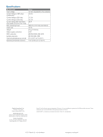
by the autopilot) 12. 5 A 17. 5 A 22. 5 A 25 A 6900 N (1,551 lbf) (intermittent) 12 W 9 kg (19. 84 lbs) IP67 BS EN 60945:2002 (DC) BS EN 8864:1990 5° to 35°C (41° to 95°F) -15° to 50°C (5° to 122°F) Garmin International, Inc. 1200 East 151st Street Olathe, Kansas 66062, USA Garmin (Europe) Ltd
-
 1
1 -
 2
2 -
 3
3 -
 4
4
 |
 |

Class B Compact Drive Unit
Installation Instructions
To obtain the best performance and to avoid damage to your
boat, install this drive unit according to these instructions.
Professional installation of the drive unit is highly
recommended, because specific knowledge of rudder operation
is required to properly install the drive unit. Read all installation
instructions before proceeding with the installation. If you
experience difficulty during the installation, contact Garmin
®
Product Support.
Important Safety Information
WARNING
You are responsible for the safe and prudent operation of your
vessel. The autopilot is a tool that will enhance your capability to
operate your boat. It does not relieve you from the responsibility
of safely operating your boat. Avoid navigational hazards and
never leave the helm unattended.
See the
Important Safety and Product Information
guide in the
product box for product warnings and other important
information.
CAUTION
When in use, beware of hot motor and solenoid components
and the risk of entrapment from moving parts.
Always wear safety goggles, ear protection, and a dust mask
when drilling, cutting, or sanding.
NOTICE
To avoid damage to your boat, the autopilot system should be
installed by a qualified marine installer. Specific knowledge of
hydraulic steering componentry and marine electrical systems is
required for proper installation.
The drive unit movement must be limited by physical end stops.
Failure to install end stops will cause the drive unit to act as a
travel limiter and will damage the drive unit.
When drilling or cutting, always check what is on the opposite
side of the surface.
Registering Your Device
Help us better support you by completing our online registration
today.
•
Go to
.
•
Keep the original sales receipt, or a photocopy, in a safe
place.
Contacting Garmin Product Support
•
Go to
www.garmin.com/support
and click
Contact Support
for in-country support information.
•
In the USA, call (913) 397.8200 or (800) 800.1020.
•
In the UK, call 0808 2380000.
•
In Europe, call +44 (0) 870.8501241.
Tools Needed
•
Tiller arm (if needed)
•
End stops to limit rudder travel (if not already present on the
boat)
•
Safety glasses
•
Drill and drill bits
•
Wrenches
•
Torque wrench
•
Loctite
®
638™ retaining compound or equivalent
(recommended)
•
Hex or allen wrenches (for removing the device from the
base for maintenance or repair)
Mounting Location Considerations
NOTICE
This device should be mounted in a location that is not exposed
to extreme temperatures or conditions. The temperature range
for this device is listed in the product specifications. Extended
exposure to temperatures exceeding the specified temperature
range, in storage or operating conditions, may cause device
failure. Extreme-temperature-induced damage and related
consequences are not covered by the warranty.
When selecting a mounting location, observe these
considerations.
•
The drive unit must be installed under deck, in a location not
subject to flooding or washdown.
•
The drive unit must be mounted securely on a surface that is
able to withstand the high thrusts generated by the rudder.
•
The drive unit must be installed within specific extension and
angle limitations, as defined in the specifications at the end
of these instructions.
•
The drive unit movement must be limited by physical stops,
and not by the length of the drive unit rod, or damage to the
drive unit will occur.
•
No part of the drive unit or rod should contact the vessel,
quadrant, or tiller arm throughout the full range of movement.
•
The 10° tilt at the extremes of the stroke must not be
exceeded, or damage to the drive unit will occur.
Tiller Arm and End Stop Considerations
You can connect the drive unit to either an existing quadrant or
to a tiller arm (not included). If you do not have a quadrant or
cannot install the drive unit at your quadrant location, choose a
tiller arm that fits the diameter of your rudder post and is the
correct length for the installation location.
The supplied tiller bolt is suitable for a quadrant or tiller arm
thickness of 12 mm (0.47 in.) to 16 mm (0.63 in.).
The drive unit must not act as a rudder-movement limiter.
Physical end stops (not included) must be in place to limit the
drive-unit travel to 254 mm (10 in.) from fully retracted to fully
extended, or damage to the drive unit will occur.
Mounting the Drive Unit
Hardware is supplied to fasten the drive unit to the mounting
surface. The supplied M8 bolts, washers, and nuts are suitable
for mounting the cylinder on a surface between 12 mm (0.47 in.)
and 24 mm (0.95 in.) thick.
1
With the drive unit in the mounting location, mark the
locations of the four mounting holes on the surface.
2
Verify the marked locations.
The marked locations should be 76.2 mm (3 in.) apart .
3
Drill 8.8 mm (0.35 in.) holes through the mounting surface.
4
Secure the drive unit to the mounting surface using the
supplied M8 bolts, washers, and nuts.
5
Tighten the bolts to 17 Nm (12.5 ft-lbf).
Installing the Tiller Pin
The supplied tiller bolt is suitable for a quadrant or tiller arm
thickness of 12 to 16 mm (0.47 to 0.63 in.).
April 2013
190-01289-03_0A
Printed in the UK