Garmin GMA 240 Installation Manual
Garmin GMA 240 Manual
 |
View all Garmin GMA 240 manuals
Add to My Manuals
Save this manual to your list of manuals |
Garmin GMA 240 manual content summary:
- Garmin GMA 240 | Installation Manual - Page 1
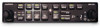
GMA 240 Installation Manual MUS IC C OM1 C OM2 SQ OFF/ VOL P ILO T 1 2 1-2 C OM1 MIC C OM2 MIC MON MUTE TEL NAV1 NAV2 AUX1 AUX2 GMA 240 P ILO T IS O IC S MUTE MUS IC R ADIO SQ 1 VOL PULL TEL MUSIC VOL C O P ILO T 190-00917-01 January, 2011 Revision B - Garmin GMA 240 | Installation Manual - Page 2
SO40 9RB U.K. +44/ (0) 870.8501241 Garmin AT, Inc. 2345 Turner Rd., SE Salem, OR 97302 USA Telephone: 503.581.8101 RECORD OF REVISIONS Revision Revision Date Description A 06/09/08 Initial Release B 01/18/11 Clarified backlighting info Page A Rev. B GMA 240 Installation Manual 190-00917-01 - Garmin GMA 240 | Installation Manual - Page 3
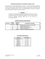
would like additional information, please refer to our web site at www.garmin.com/prop65. CURRENT REVISION DESCRIPTION Revision B Page Number i 1-1 1-5 Range i - iv 1-1 - 1-6 2-1 - 2-6 3-1 - 3-4 4-1 - 4-8 A-1 - A-6 B-1 - B-8 C-1 - C-2 GMA 240 Installation Manual 190-00917-01 Page i Revision B - Garmin GMA 240 | Installation Manual - Page 4
...2-1 2.2 Installation Materials ...2-1 2.3 GMA 240 Wiring, Configuration, and Adjustment Options 2-1 2.4 Noise ...2-5 2.5 GMA 240 Mounting ...2-6 3 INSTALLATION PROCEDURE...3-1 3.1 Unpacking Unit...3-1 3.2 Electrical Connections ...3-1 3.3 Audio Shield Termination ...3-2 3.4 GMA 240 Installation - Garmin GMA 240 | Installation Manual - Page 5
2.5 mm Plug Used with P2403 ...4-4 A-1 GMA 240 Outline Drawing ...A-1 A-2 GMA 240 Connector/Rack Assembly Drawing A-3 A-3 GMA 240 Recommended Panel Cutout Dimensions A-5 B-1 GMA 240 Interconnect Drawing (page 1 of 3 B-1 B-1 GMA 240 Interconnect Drawing (page 2 of 3 B-3 B-1 GMA 240 Interconnect - Garmin GMA 240 | Installation Manual - Page 6
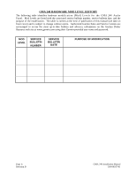
up-to-date bulletin and advisory information on the Garmin Dealer Resource web site at www.garmin.com using their Garmin-provided user name and password. MOD LEVEL SERVICE BULLETIN NUMBER SERVICE BULLETIN DATE PURPOSE OF MODIFICATION Page iv Revision B GMA 240 Installation Manual 190-00917-01 - Garmin GMA 240 | Installation Manual - Page 7
1.1 Introduction This manual provides the installation instructions for the Garmin GMA 240 Audio Panel. Reference to GMA 240 throughout this manual refers to all versions of the unit. Information pertaining to the maintenance of the unit can be found in the GMA 240 Maintenance Manual, P/N 190-00917 - Garmin GMA 240 | Installation Manual - Page 8
Height Bezel Width Rack Height (Dimple to Dimple) Rack Width Depth Behind Panel with Connectors (measured from face of aircraft panel to rear of connector backshells) GMA 240 Weight (Unit Only) GMA 240 Weight (Installed with rack and connectors) Specification 1.30 inches (33 mm) 6.29 inches (159 - Garmin GMA 240 | Installation Manual - Page 9
°C (operation) -55°C to +85°C (storage) Altitude 55,000 Feet Audio Panel Functions configure for all, crew) Telephone interfaces: 1 full-duplex (use LRU pins or front jack) Headphone Outputs Output amplifiers: distortion and bandwidth GMA 240 Installation Manual 190-00917-01 Page 1-3 Rev. B - Garmin GMA 240 | Installation Manual - Page 10
information for installing the GMA 240. Before installing the unit, the technician should read all referenced materials along with this manual. Part Number 190-00917-00 190-00917-02 Document GMA 240 Pilot's Guide GMA 240 Maintenance Manual Page 1-4 Rev. B GMA 240 Installation Manual 190-00917 - Garmin GMA 240 | Installation Manual - Page 11
1200 East 151st Street Olathe, Kansas 66062, U.S.A. Phone: 913/397.8200 FAX: 913/397.0836 Garmin (Europe) Ltd. Liberty House, Bulls Copse Road Hounsdown Business Park Romsey, SO40 9RB, U.K. Phone: 44/ (0) 870.8501241 FAX: 44/ (0) 870.850125 GMA 240 Installation Manual 190-00917-01 Page 1-5 Rev. B - Garmin GMA 240 | Installation Manual - Page 12
This page intentionally left blank Page 1-6 Rev. B GMA 240 Installation Manual 190-00917-01 - Garmin GMA 240 | Installation Manual - Page 13
wiring diagrams, mounting dimensions, and information pertaining to installation. 2.2 Installation Materials 2.2.1 Equipment Available GMA 240 Audio Panel, Ship Level Assembly, P/N 010-00735-() includes the following, depending on part number: Item Connector Kit, GMA 340 Rack Backplate, GMA 340 - Garmin GMA 240 | Installation Manual - Page 14
location. This service should only be performed by a qualified technician. Garmin is not responsible for damage caused during adjustment of these internal configuration jumper settings. Refer to the GMA 240 Maintenance Manual for disassembly/reassembly instructions. The GMA 240 contains static - Garmin GMA 240 | Installation Manual - Page 15
against unintended components or circuit board paths. Use a 2 mm (max blade width) flat-blade non-conductive screw driver or adjustment tool. CW adjustment increases the levels for volume inputs and for the mute threshold for radio inputs. GMA 240 Installation Manual 190-00917-01 Page 2-3 Rev. B - Garmin GMA 240 | Installation Manual - Page 16
the MASQ threshold. This increases background noise during otherwise quiet operation because noise from these inputs is not squelched. This option is most useful as a troubleshooting tool. CREW ISO: This input configures the audio panel for crew intercom isolation in place of pilot isolation. When - Garmin GMA 240 | Installation Manual - Page 17
operating in the aircraft. These differences in potential can produce an additive effect at an audio panel signal input. The audio panel important. The wiring diagrams and accompanying notes in this manual should be followed closely to minimize noise effects. GMA 240 Installation Manual 190-00917 - Garmin GMA 240 | Installation Manual - Page 18
). The GMA 240 is mounted using a GMA 340 unit rack. Figure 2-2 shows the GMA 340 unit rack. See Section 3.4 for installation instructions. NOTE Rear support is recommended to ensure a sturdy mount. Figure 2-2. GMA 340 Unit Rack (115-00262-00) Page 2-6 Rev. B GMA 240 Installation Manual 190-00917 - Garmin GMA 240 | Installation Manual - Page 19
of the connector when using an extractor due to the absence of the wire. A new contact must be used when reassembling the connector. 3. For applications using 16 AWG wire, contact Garmin for information regarding connector crimp positioner tooling. GMA 240 Installation Manual 190-00917-01 Page - Garmin GMA 240 | Installation Manual - Page 20
in Figure 3-1. Rear View of backplate and rack J2402 J2401 Audio shields daisy chained and terminated using a lug attached to either of these screws. Figure 3-1. Audio Shield Termination 3.4 GMA 240 Installation NOTE Avoid installing the unit near heat sources. If this is not possible, ensure - Garmin GMA 240 | Installation Manual - Page 21
operation in systems with limited power budgets. In the case of copilot/passenger positions wired in parallel, any stereo listener will lose right channel audio when another passenger plugs in a mono headset. 1. Set the intercom to the ALL mode [Pilot ISO LED off.] GMA 240 Installation Manual - Garmin GMA 240 | Installation Manual - Page 22
Manual (Garmin P/N 190-00917-02) as needed. Periodic maintenance of the GMA 240 is not required. Instructions for Continued Airworthiness (ICA) are not required for this product under 14 CFR Part 21 since the GMA 240 has received no FAA approval or endorsement. Page 3-4 Rev. B GMA 240 Installation - Garmin GMA 240 | Installation Manual - Page 23
4 SYSTEM INTERCONNECTS 4.1 Connector Description The GMA 240 has two 44-pin connectors located at the rear of the unit designated J2401 and J2402 are connected to ground to activate. Active low outputs sink current to ground when active. GMA 240 Installation Manual 190-00917-01 Page 4-1 Rev. B - Garmin GMA 240 | Installation Manual - Page 24
PASS HEADSET AUDIO OUT LO 43 ALERT 2,3 AUDIO IN LO 44 ALERT 2 AUDIO IN HI * Denotes Active Low (Inputs: ground to activate; Outputs: grounded when active) I/O --IN -OUT -IN -IN -OUT OUT IN -OUT IN IN -IN -IN -------IN OUT IN -IN IN -----OUT OUT --IN Page 4-2 Rev. B GMA 240 Installation Manual 190 - Garmin GMA 240 | Installation Manual - Page 25
IN HI 36 PASS 1 MIC AUDIO IN LO 37 PASS 2 MIC AUDIO IN HI 38 PASS 2 MIC AUDIO IN LO 39 RESERVED 40 RESERVED 41 RESERVED 42 RESERVED 43 RESERVED 44 RESERVED * Denotes Active Low (Inputs: ground to activate; Outputs: grounded when active) GMA 240 Installation Manual 190-00917-01 I/O --OUT OUT -IN - Garmin GMA 240 | Installation Manual - Page 26
is controlled by a photocell that operates independently of the backlight input. Pin Connector Pin Name I/O 5 P2402 LIGHTING BUS 14V LO/28V LO -- 6 P2402 LIGHTING BUS 14V HI/28V LO IN 7 P2402 LIGHTING BUS 14V HI/28V HI IN Page 4-4 Rev. B GMA 240 Installation Manual 190-00917-01 - Garmin GMA 240 | Installation Manual - Page 27
wired as normal. In this mode, when the PILOT ISO button is selected, the pilot and copilot will hear each other, but will be intercom isolated from the passengers. 13 P2402 PILOT ISO Ground to allow Music audio Low (Ground to activate) GMA 240 Installation Manual 190-00917-01 Page 4-5 Rev. B - Garmin GMA 240 | Installation Manual - Page 28
if the audio panel has been AUDIO IN HI COM 2 Audio Input 15 P2401 COM 2 MIC AUDIO OUT HI COM 2 Audio Output 14 P2401 COM 2 AUDIO LO Ground Reference for COM 2 * Denotes Active Low (Sinks current to ground when active) I/O OUT OUT IN OUT -IN OUT -- Page 4-6 Rev. B GMA 240 Installation Manual - Garmin GMA 240 | Installation Manual - Page 29
2 IN LEFT MUSIC 2 IN RIGHT MUSIC 2 IN LO Description I/O Music 1 Input IN IN Ground Reference for Music 1 -- Music 2 Input IN IN Ground Reference for Music 2 -- GMA 240 Installation Manual 190-00917-01 Page 4-7 Rev. B - Garmin GMA 240 | Installation Manual - Page 30
Audio Output Passenger Headset Audio Output I/O OUT OUT -OUT OUT -OUT OUT -- NOTE Copilot and Passenger headset outputs are internally the same connection. Separate Passenger headset output pins are provided for wiring convenience and GMA 340 4-8 Rev. B GMA 240 Installation Manual 190-00917-01 - Garmin GMA 240 | Installation Manual - Page 31
APPENDIX A OUTLINE AND INSTALLATION DRAWINGS GMA 240 Installation Manual 190-00917-01 Figure A-1. GMA 240 Outline Drawing Page A-1 (Page A-2 blank) Rev B - Garmin GMA 240 | Installation Manual - Page 32
APPENDIX A OUTLINE AND INSTALLATION DRAWINGS GMA 240 Installation Manual 190-00917-01 Figure A-2. GMA 240 Connector/Rack Assembly Drawing Page A-3 (Page A-4 blank) Rev B - Garmin GMA 240 | Installation Manual - Page 33
APPENDIX A OUTLINE AND INSTALLATION DRAWINGS GMA 240 Installation Manual 190-00917-01 Figure A-3. GMA 240 Recommended Panel Cutout Dimensions Page A-5 (Page A-6 blank) Rev B - Garmin GMA 240 | Installation Manual - Page 34
APPENDIX B INTERCONNECT DRAWINGS GMA 240 Installation Manual 190-00917-01 Figure B-1. GMA 240 Interconnect Drawing (page 1 of 3) Page B-1 (Page B-2 blank) Rev B - Garmin GMA 240 | Installation Manual - Page 35
APPENDIX B INTERCONNECT DRAWINGS GMA 240 Installation Manual 190-00917-01 Figure B-1. GMA 240 Interconnect Drawing (page 2 of 3) Page B-3 (Page B-4 blank) Rev B - Garmin GMA 240 | Installation Manual - Page 36
APPENDIX B INTERCONNECT DRAWINGS 10. IF PINS 5, 6, & 7 ARE NOT CONNECTED IN THE 14V OR 28V CONFIGURATION, BACKLIGHTING WILL NOT FUNCTION (NO BACKLIGHTING). GMA 240 Installation Manual 190-00917-01 Figure B-1. GMA 240 Interconnect Drawing (page 3 of 3) Page B-5 (Page B-6 blank) Rev B - Garmin GMA 240 | Installation Manual - Page 37
IN LO PASS 2 MIC PASS 1 MIC AUDIO IN HI AUDIO IN LO PASS 1 MIC AUDIO IN HI COPILOT MIC COPILOT MIC COPILOT MIC AUDIO IN LO KEY* IN AUDIO IN HI PILOT HEADSET AUDIO OUT RIGHT GMA 240 Installation Manual 190-00917-01 Figure B-2. GMA 240, J2401 & J2402 Connector Layout Drawing Page B-7 (Page - Garmin GMA 240 | Installation Manual - Page 38
APPENDIX C CONFIGURATION JUMPERS DRAWING Top of Main Board Bottom of Main Board GMA 240 Installation Manual 190-00917-01 Figure C-1. GMA 240, Internal Configuration Jumper Layout Drawing Page C-1 (Page C-2 blank) Rev B
-
 1
1 -
 2
2 -
 3
3 -
 4
4 -
 5
5 -
 6
6 -
 7
7 -
8
-
9
-
10
-
11
-
12
-
13
-
14
-
15
-
16
-
17
-
18
-
19
-
20
-
21
-
22
-
23
-
24
-
25
-
26
-
27
-
28
-
29
-
30
-
31
-
32
-
33
-
34
-
35
-
36
-
37
-
38
 |
 |

190-00917-01
January, 2011
Revision B
GMA 240
Installation Manual
PILOT
COPILOT
MUTE
MON
SQ
OFF/
VOL
SQ
VOL
PULL
MUSIC
VOL
TEL
GMA 240
PILOT
ISO
MUTE MUSIC
MUSIC
ICS
RADIO
NAV1
NAV2
AUX1
AUX2
COM1
MIC
COM1
COM2
COM2
MIC
TEL
1
1-2
1
2