Garmin GMI 20 Installation Instructions
Garmin GMI 20 Manual
 |
View all Garmin GMI 20 manuals
Add to My Manuals
Save this manual to your list of manuals |
Garmin GMI 20 manual content summary:
- Garmin GMI 20 | Installation Instructions - Page 1
To obtain the best possible performance, install this marine instrument according to these instructions. If you experience difficulty during the installation, contact Garmin® Support, or seek the advice of a professional installer. This instrument communicates with NMEA 2000® sensors and devices - Garmin GMI 20 | Installation Instructions - Page 2
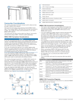
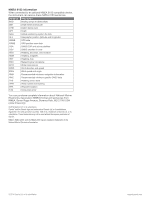
2000 Network Fundamentals" chapter of the Technical Reference for NMEA 2000 Products. To download the reference, go to garmin.com/manuals/nmea_2000. Wind transducer GND 10 black box bridge Marine instrument Ignition or in-line switch NMEA 2000 power cable NMEA 2000 drop cable Power source NMEA 2000 - Garmin GMI 20 | Installation Instructions - Page 3
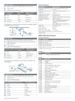
Garmin HVS GPS antenna. Item Description Marine instrument with a NMEA data cable (not included) Power source Garmin HVS GPS antenna Item Marine Instrument (DOP) Wind data Environmental parameters Environmental parameters Temperature Humidity Actual pressure GMI 20 Installation Instructions 3 - Garmin GMI 20 | Installation Instructions - Page 4
the instrument can Garmin Ltd. or its subsidiaries. These trademarks may not be used without the express permission of Garmin. NMEA®, NMEA 2000®, and the NMEA 2000 logo are registered trademarks of the National Marine Electronics Association. © 2014 Garmin Ltd. or its subsidiaries support.garmin
-
 1
1 -
 2
2 -
 3
3 -
 4
4
 |
 |
GMI 20 Installation Instructions
To obtain the best possible performance, install this marine
instrument according to these instructions. If you experience
difficulty during the installation, contact Garmin
®
Support, or seek
the advice of a professional installer.
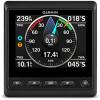
This instrument communicates with NMEA 2000
®
sensors and
devices, and shows information such as speed, heading, and
water depth when connected to the appropriate sensors. The
instrument can also communicate with a NMEA
®
0183 device
using an optional data cable.
Important Safety Information
WARNING
See the
Important Safety and Product Information
guide in the
product box for product warnings and other important
information.
CAUTION
Always wear safety goggles, ear protection, and a dust mask
when drilling, cutting, or sanding.
NOTICE
When drilling or cutting, always check what is on the opposite
side of the surface.
Mounting Considerations
NOTICE
This device should be mounted in a location that is not exposed
to extreme temperatures or conditions. The temperature range
for this device is listed in the product specifications. Extended
exposure to temperatures exceeding the specified temperature
range, in storage or operating conditions, may cause device
failure. Extreme-temperature-induced damage and related
consequences are not covered by the warranty.
The mounting surface must be flat to avoid damaging the device
when it is mounted.
Using the included hardware and template, you can flush mount
the device in the dashboard. If you want to mount the device
using an alternative method where it appears flat with the front
of the dashboard, you must purchase a flat-mount kit
(professional installation recommended) from your Garmin
dealer.
When selecting a mounting location, observe these
considerations.
•
The mounting location should be at or below eye level to
provide optimal viewing as you operate your vessel.
•
The mounting location should allow easy access to the keys
on the device.
•
The mounting surface must be strong enough to support the
weight of the device and protect it from excessive vibration or
shock.
•
To avoid interference with a magnetic compass, the device
should not be installed closer to a compass than the
compass-safe distance value listed in the product
specifications.
•
The area behind the mounting surface must allow room for
the routing and connection of the cables.
Mounting the Device
NOTICE
If you are mounting the device in fiberglass, when drilling the
pilot holes, it is recommended to use a countersink bit to drill a
clearance counterbore through only the top gel-coat layer. This
will help to avoid cracking in the gel-coat layer when the screws
are tightened.
Stainless-steel screws may bind when screwed into fiberglass
and overtightened. It is recommended to apply an anti-seize
lubricant on the screws before installing them.
The included template and hardware can be used to flush mount
the device in your dashboard.
1
Trim the flush-mount template and ensure it fits in the
location where you plan to mount the marine instrument.
The flush-mount template is included in the product box.
2
Remove the liner from the adhesive on the back of the
template and adhere it to the location where you plan to
mount the marine instrument.
3
If you plan to cut the hole using a rotary tool instead of a
90 mm (3.5 in.) hole saw, use a 10 mm (
3
/
8
in.) drill bit to drill
a pilot hole to begin cutting the mounting surface.
4
Using the 90 mm (3.5 in.) hole saw or rotary tool, cut the
mounting surface along the inside of the dashed line
indicated on the flush-mount template.
5
If necessary, use a file and sandpaper to refine the size of
the hole.
6
Place the marine instrument into the cutout to confirm that
the mounting holes on the template are in the correct
locations.
7
If the mounting holes are not correct, mark the correct
locations of the mounting holes.
8
Remove the marine instrument from the cutout.
9
Drill the 2.8 mm (
7
/
64
in.) pilot holes.
If you are mounting the marine instrument in fiberglass, use a
countersink bit as advised in the notice.
10
Remove the remainder of the template.
11
Place the included gasket on the back of the device and
apply marine sealant around the gasket to prevent leakage
behind the dashboard.
12
If you will not have access to the back of the device after you
mount it, connect all necessary cables to the device before
placing it into the cutout.
NOTE:
To prevent corrosion of the metal contacts, cover
unused connectors with the attached weather caps.
13
Place the marine instrument into the cutout.
14
Securely fasten the marine instrument to the mounting
surface using the supplied screws.
If you are mounting the marine instrument in fiberglass, use a
anti-galling lubricant as advised in the notice.
15
Snap the bezel
into place.
GUID-D193C1DF-4085-4AE2-9B92-78318B159AFD v4
August 2020