Garmin GMR 24 xHD Marine Ethernet Install Instructions
Garmin GMR 24 xHD Manual
 |
View all Garmin GMR 24 xHD manuals
Add to My Manuals
Save this manual to your list of manuals |
Garmin GMR 24 xHD manual content summary:
- Garmin GMR 24 xHD | Marine Ethernet Install Instructions - Page 1
Marine Ethernet Installation Instructions The Garmin Marine Network is an Ethernet network used to share data such as radar, sonar, and detailed mapping. You can modify the Ethernet cable to suit your installation needs. To obtain the best performance and to avoid damage to - Garmin GMR 24 xHD | Marine Ethernet Install Instructions - Page 2
Garmin® and the Garmin logo are trademarks of Garmin Ltd. or its subsidiaries, registered in the USA and other countries. These trademarks may not be used without the express permission of Garmin. © 2004 Garmin Ltd. or its subsidiaries www.garmin.com/support
-
 1
1 -
 2
2
 |
 |
Marine Ethernet Installation
Instructions
The Garmin Marine Network is an Ethernet network used to
share data such as radar, sonar, and detailed mapping. You
can modify the Ethernet cable to suit your installation needs. To
obtain the best performance and to avoid damage to your boat,
install the connector according to these instructions. Read all
installation instructions before proceeding with the installation. If
you experience difficulty during the installation, contact Garmin
Product Support.
Contacting Garmin Product Support
•
Go to
www.garmin.com/support
and click
Contact Support
for in-country support information.
•
In the USA, call (913) 397.8200 or (800) 800.1020.
•
In the UK, call 0808 2380000.
•
In Europe, call +44 (0) 870.8501241.
Important Safety Information
WARNING
See the
Important Safety and Product Information
guide in the
product box for product warnings and other important
information.
CAUTION
Always wear safety goggles, ear protection, and a dust mask
when drilling, cutting, or sanding.
NOTICE
When drilling or cutting, always check what is on the opposite
side of the surface.
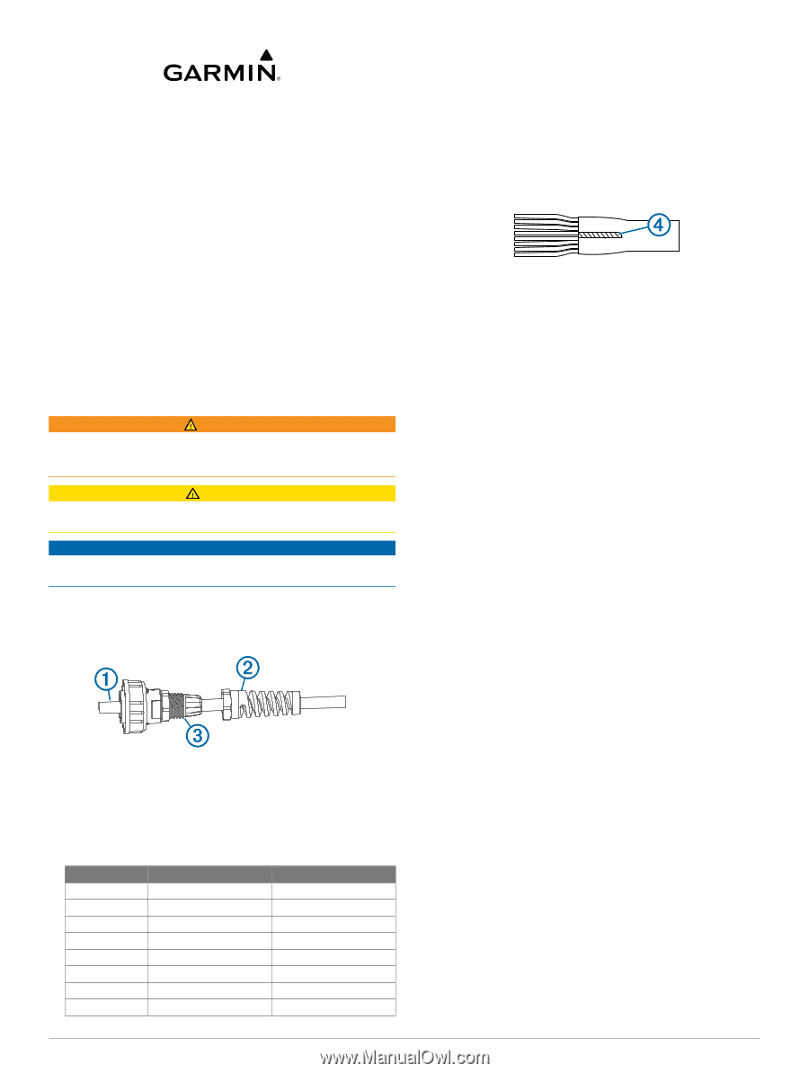
Preparing the Network Cable
1
Cleanly cut the Ethernet cable
À
to the needed length.
NOTE:
Retain the connector for use in step 4.
2
Remove the strain-relief nut
Á
from the cable-connection
housing
Â
and slide the nut onto the cut end of the Ethernet
cable.
3
Feed the cut cable end through the connection housing.
4
Examine the connector removed from the cable and
compare it to this table to determine whether cable side A or
cable side B was removed.
Position
Side A
Side B
1
White/Orange
White/Green
2
Orange
Green
3
White/Green
White/Orange
4
Blue
Blue
5
White/Blue
White/Blue
6
Green
Orange
7
White/Brown
White/Brown
8
Brown
Brown
NOTE:
As a point of reference, the brown wire will always be
in position 8.
NOTE:
The Garmin Marine Network requires cross-over
cables not exceeding 100 m between devices.
5
Using a sharp knife, insert the blade between the cable
shield and jacket, and slit the jacket 16 mm (
5
/
8
in.) from the
cut end of the cable.
6
Peel the jacket back and remove the slit portion.
7
Trim the drain wire
Ã
to approximately 14 mm (
9
/
16
in.) and
fold the drain wire back over the jacket.
8
Arrange the individual wires in order according to table
shown in step 4.
NOTE:
When constructing a custom cable from bulk wire,
you must create both a side A and a side B.
9
Trim the wires to an even length, leaving approximately
14 mm (
9
/
16
in.) from the ends of the wires to the jacket edge.
10
Wrap the supplied copper tape around the drain wire and
jacket.
11
Using a pair of pliers, squeeze the copper tape to pre-form
the cable jacket end.
Installing the Network Connector
1
With the wires in the correct order, insert the wires into the
modular plug until the ends of the wires touch the bottom of
the plug.
2
Verify the wires are in the correct order.
3
If any wire is not in the correct position, remove the plug,
arrange the wires in the correct order, and reinsert the wires
into the plug.
4
Using a modular plug hand tool, crimp the plug onto the
wires.
5
Align the release tab on the modular plug with the
corresponding notch in the cable-connection housing, and
push the cable through the connection housing until plug is
securely seated.
6
Screw the strain relief nut onto the cable-connection housing
and tighten with a 15 mm wrench.
NOTE:
Do not overtighten the nut.
7
Install the O-ring onto the housing.
The cable is now ready for use.
April 2014
190-00489-00_0C
Printed in Taiwan