Garmin GMR 24 xHD Installation Instructions
Garmin GMR 24 xHD Manual
 |
View all Garmin GMR 24 xHD manuals
Add to My Manuals
Save this manual to your list of manuals |
Garmin GMR 24 xHD manual content summary:
- Garmin GMR 24 xHD | Installation Instructions - Page 1
This device contains no user-serviceable parts, and should be opened only by a Garmin® authorized service technician. Any damage resulting from when you install this device. For instructions on updating the software, see your chartplotter owner's manual at support.garmin.com. Tools Needed • Drill - Garmin GMR 24 xHD | Installation Instructions - Page 2
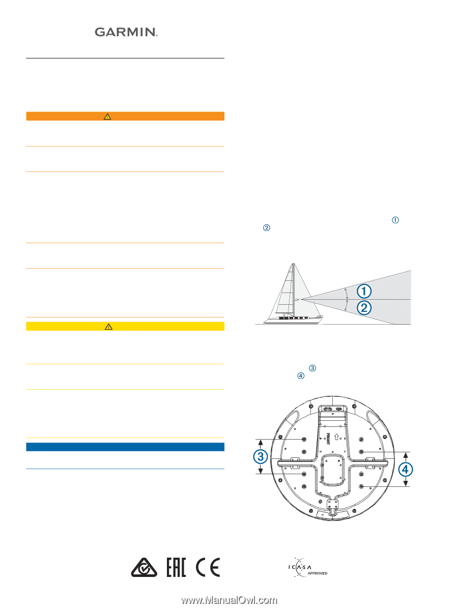
.) mounting holes. 2 Connect the power cable to the power port and the network cable to the network port . 3 Press the cables into any of the guide grooves on the bottom of the case, and secure them using a cable holddown plate . The cables should be bent or twisted as little as possible - Garmin GMR 24 xHD | Installation Instructions - Page 3
functions of this radar are controlled with your Garmin chartplotter. See the Radar section of your chartplotter's owner's manual for operating instructions. To download the latest manual, go to support.garmin.com. If you have more than one radar on your boat, you must be viewing the radar screen - Garmin GMR 24 xHD | Installation Instructions - Page 4
Cable Extensions section of these instructions to make sure the correct help troubleshoot installation problems. support for assistance. Contacting Garmin Support • Go to support.garmin.com for help and information, such as product manuals, frequently asked questions, videos, and customer support
-
 1
1 -
 2
2 -
 3
3 -
 4
4
 |
 |
GMR
™
18
XHD/24
XHD/18
HD+
INSTALLATION
INSTRUCTIONS
Important Safety Information
WARNING
Failure to follow these warnings, cautions, and notices could
result in personal injury, damage to the vessel or device, or poor
product performance.
See the
Important Safety and Product Information
guide in the
product box for product warnings and other important
information.
The radar transmits electromagnetic energy. To avoid possible
personal injury, damage to the vessel or device, or poor product
performance, ensure that the radar is installed according to the
recommendations in these instructions and that all personnel
are clear of the path of the radar beam before transmitting.
When properly installed and operated, the use of this radar
conforms to the requirements of ANSI/IEEE C95.1-1992
Standard for Safety Levels with Respect to Human Exposure to
Radio Frequency Electromagnetic Fields.
To avoid possible personal injury, do not look directly at the
antenna at close range when the radar is transmitting. Eyes are
the most sensitive part of the body to electromagnetic energy.
When connecting the power cable, do not remove the in-line
fuse holder. To prevent the possibility of injury or product
damage caused by fire or overheating, the appropriate fuse
must be in place as indicated in the product specifications. In
addition, connecting the power cable without the appropriate
fuse in place voids the product warranty.
CAUTION
This device should be used only as a navigational aid. Using the
device for any purpose requiring precise measurement or
direction, distance, location, or topography may result in
personal injury or damage to the vessel.
To avoid possible personal injury, always wear safety goggles,
ear protection, and a dust mask when drilling, cutting, or
sanding.
Opening the device may result in personal injury and/or damage
to the device. This device contains no user-serviceable parts,
and should be opened only by a Garmin
®
authorized service
technician. Any damage resulting from opening the unit by
anyone other than a Garmin authorized service technician will
not be covered by the Garmin warranty.
NOTICE
When drilling or cutting, always check what is on the opposite
side of the surface to avoid damaging the vessel.
Software Update
You must update the Garmin chartplotter software when you
install this device. For instructions on updating the software, see
your chartplotter owner's manual at
support.garmin.com
.
Tools Needed
•
Drill
•
9.5 mm (
3
/
8
in.) drill bit
•
32 mm (1
1
/
4
in.) drill bit (optional)
•
4 mm (
13
/
32
in.) hex wrench
•
13 mm (
1
/
2
in.) wrench and torque wrench
•
Marine sealant
Mounting Considerations
To complete the installation, you need the appropriate fasteners,
tools, and mounts. These items are available at most marine
dealers.
•
It is highly recommended that the device is mounted out of
range of personnel, with the horizontal beam width above
head height. To avoid exposure to harmful radio frequency
(RF) levels, the device should not be mounted closer to
people than the maximum safe distance value listed in the
product specifications.
•
The device should be mounted high above the ship’s keel
line with minimal blockage between the vessel and the radar
beam. Obstructions may cause blind and shadow sectors, or
generate false echoes. The higher the installation position,
the farther the radome can detect targets.
•
The device should be mounted on a flat surface or a platform
that is parallel to the vessel's water line and is sturdy enough
to support the device's weight. The weight for each model is
listed in the product specifications.
•
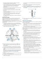
Most radar beams spread vertically 12.5° above
and 12.5°
below
the radome's radiating element. On vessels with
higher bow angles at cruise speed, the installation angle can
be lowered to point the beam slightly downward to the
waterline while at rest. Use shims if necessary.
•
The radome has two mounting options when installed on a
standard marine mount. One mounting option is closer to the
center of the radome
, and the second option is offset
towards the back
to move the radar further away from the
mast.
•
The device should be mounted away from heat sources such
as smoke stacks and lights.
TA-2013/1848
2302
GUID-FEFFD103-E5C5-42E2-9628-C69074C658E1 v5
August 2020