Garmin GPS 17HVS Installation Guide
Garmin GPS 17HVS - Receiver Module Manual
 |
UPC - 753759052546
View all Garmin GPS 17HVS manuals
Add to My Manuals
Save this manual to your list of manuals |
Garmin GPS 17HVS manual content summary:
- Garmin GPS 17HVS | Installation Guide - Page 1
GPS 17 GPS receiver/antenna installation guide - Garmin GPS 17HVS | Installation Guide - Page 2
written consent of Garmin. Garmin hereby grants permission to download a single copy of this manual onto a hard Garmin. Note: Operation of this device is subject to the following conditions: (1) This device may not cause harmful interference, and (2) this device must accept any interference received - Garmin GPS 17HVS | Installation Guide - Page 3
www.rtcm.org GPS 17 Installation Guide INTRODUCTION Introduction i Specifications 1 Mounting the Receiver 2 Mounting Location Tips 3 Routing the Cable 5 Wiring the GPS 17 6 Wire Color Code 6 Wiring Diagrams 7 Using the GPS 17 10 First Time Fix 10 Limited Warranty 11 This manual uses the - Garmin GPS 17HVS | Installation Guide - Page 4
information received from the GPS 17 to all GPS 17 only to facilitate, not to replace garmin.com/prop65. Caution Failure to avoid the following potentially hazardous situations may result in injury or property damage. Use the GPS 17 only as a navigational aid. Do not attempt to use the GPS 17 - Garmin GPS 17HVS | Installation Guide - Page 5
Current: - Garmin GPS 17HVS | Installation Guide - Page 6
GPS 17 Thoroughly read and completely understand these instructions before attempting the installation. When in doubt, seek professional assistance. You can use an antenna mount to install the GPS 17. The receiver base fits a standard 1-inch, 14 threads-per-inch marine mount. Check with your Garmin - Garmin GPS 17HVS | Installation Guide - Page 7
the receiver at least three feet from all other antennas and the vessel's electrical system components (alternator/ignition system). • The GPS 17 is supplied with a 30-foot power/data cable. Be sure that the cable can be routed to the necessary devices. GPS 17 Installation Guide MOUNTING THE GPS 17 - Garmin GPS 17HVS | Installation Guide - Page 8
the point that the cable may be cut in two. 3. Fill the remaining gap in the cable exit with marine sealant. Figure 2: Attaching the Pole Mount to the Base Figure 3: Running the Cable Outside of the Mount 4 GPS 17 Installation Guide - Garmin GPS 17HVS | Installation Guide - Page 9
the marked location. 3. Slide the cable through the mount and screw the GPS 17 onto the mount. 4. Fasten the mount to the boat. MOUNTING THE GPS 17 Routing the Cable You can shorten or coil excess or bending the cable. Figure 4: Running the Cable Through the Mount GPS 17 Installation Guide 5 - Garmin GPS 17HVS | Installation Guide - Page 10
After mounting the GPS 17 in the desired location, connect the wiring. Connect the GPS 17's Port 1 Data In, Data Out, Remote On/Off, and Ground (Return) lines to your NMEA device or PC. Port 2 is used for RTCM input only. For reliable communication, it is essential that the GPS 17 and the receiving - Garmin GPS 17HVS | Installation Guide - Page 11
) Yellow (On/Off) Blue (Data In) > White (Data Out) > > Figure 5: NMEA and GPS 17 Wiring GPS 17 Closed = On Open = Off GPS 17 Installation Guide Power Source 8-40 Volts DC Fuse Red (Power) 1 A Black (Ground) Yellow (On/Off) Switch Figure 6: GPS 17 Switch Wiring WIRING THE GPS 17 GPS 17 7 - Garmin GPS 17HVS | Installation Guide - Page 12
Yellow (On/Off) White (Port 1 Data Out) Green (Port 2 Data In) Figure 7: DGPS GBR 21/23 and GPS 17 Wiring GPS 17 DB-9 Serial PC Connector* 1 2 3 4 5 6 7 8 9 Pin 5: Ground > Pin 3: Data Out Pin pin numbers printed next to each pin. Figure 8: DB-9 and GPS 17 Wiring 8 GPS 17 Installation Guide - Garmin GPS 17HVS | Installation Guide - Page 13
applied/removed to the Red (+) wire. If a remote power switch is being installed, refer to Figure 6 on page 7. This will allow the GPS 17 to remain connected to a power source but manually powered on (pull down to less than 0.5 volts) and off (open). Some non-Garmin devices may have a separate data - Garmin GPS 17HVS | Installation Guide - Page 14
17, refer to the GPS 16/17 Technical Specifications located on the Garmin Web site. WAAS Capability The GPS 17 can receive WAAS (Wide Area Augmentation System) satellite signals. WAAS is an FAA-funded project to improve the overall integrity of the GPS signal and increase position accuracy for users - Garmin GPS 17HVS | Installation Guide - Page 15
unit or software or offer a full refund of the purchase price at its sole discretion. SUCH REMEDY SHALL BE YOUR SOLE AND EXCLUSIVE REMEDY FOR ANY BREACH OF WARRANTY. To obtain warranty service, contact your local Garmin authorized dealer or call Garmin Product Support for shipping instructions and - Garmin GPS 17HVS | Installation Guide - Page 16
the latest free software updates (excluding map data) throughout the life of your Garmin products, visit the Garmin Web site at www.garmin.com. © Copyright 2005 Garmin Ltd. or its subsidiaries Garmin International, Inc. 1200 East 151st Street, Olathe, Kansas 66062, U.S.A. Garmin (Europe) Ltd. Unit
-
 1
1 -
 2
2 -
 3
3 -
 4
4 -
 5
5 -
 6
6 -
 7
7 -
8
-
9
-
10
-
11
-
12
-
13
-
14
-
15
-
16
 |
 |

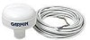
GPS 17
GPS receiver/antenna
installation guide