Garmin GPSMAP 8700 Black Box Installation Instructions PDF
Garmin GPSMAP 8700 Black Box Manual
 |
View all Garmin GPSMAP 8700 Black Box manuals
Add to My Manuals
Save this manual to your list of manuals |
Garmin GPSMAP 8700 Black Box manual content summary:
- Garmin GPSMAP 8700 Black Box | Installation Instructions PDF - Page 1
GPSMAP® 8700 INSTALLATION INSTRUCTIONS Important Safety Information WARNING See the Important Safety and Product Information guide in the product box information, see the owner's manual at www.garmin.com/manuals/GPSMAP8700. Registering Your Device Help us better support you by completing our online - Garmin GPSMAP 8700 Black Box | Installation Instructions PDF - Page 2
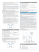
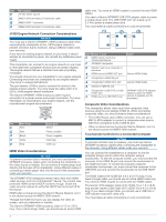
(+) battery terminal, and connect the black wire to the negative (-) battery terminal GPSMAP 8700 device on or off. Using the power key on the GRID 20 device will place the GPSMAP 8700 device into sleep mode. • Another Garmin chartplotter • A GMM™ monitor When power is applied to the GPSMAP 8700 - Garmin GPSMAP 8700 Black Box | Installation Instructions PDF - Page 3
8700 device or to the same Garmin Marine Network as the GPSMAP 8700 device. • The touch data is sent over the Garmin Marine Network. Item Device or port GPSMAP chartplotter GMM touchscreen monitor Chartplotter's HDMI OUT port GMM monitor's MAIN DVI VIDEO IN port GMM monitor's GARMIN PROCESSOR BOX - Garmin GPSMAP 8700 Black Box | Installation Instructions PDF - Page 4
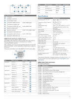
. The GPSMAP 8700 chartplotter allows video input from HDMI video sources, such as a Chromecast™ device. You cannot view protected HDMI content (HDCP content), though. Check the video source's manual to verify that HDCP can be turned off for the source. HDMI video is shared across the Garmin Marine - Garmin GPSMAP 8700 Black Box | Installation Instructions PDF - Page 5
shield) Spare Wire Color Yellow Orange Black N/A Pin Number Item Device or port Computer GPSMAP chartplotter Touchscreen monitor Computer's HDMI OUT OTG port Computer's USB HOST port Cable Garmin HDMI Cable Garmin HDMI Cable Garmin OTG Adapter Cable Garmin USB Cable NMEA 0183 with Audio Cable - Garmin GPSMAP 8700 Black Box | Installation Instructions PDF - Page 6
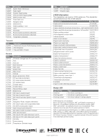
gas temperature - left manifold 65031 2434 Engine auxiliary coolant 65172 Active diagnostic trouble codes 65226 Vehicle distance 65248 Water in fuel indicator 65279 Engine wait to a registered trademark of Microsoft Corporation in the United States and other countries. support.garmin.com
-
 1
1 -
 2
2 -
 3
3 -
 4
4 -
 5
5 -
 6
6
 |
 |

GPSMAP
®
8700
INSTALLATION
INSTRUCTIONS
Important Safety Information
WARNING
See the
Important Safety and Product Information
guide in the
product box for product warnings and other important
information.
When connecting the power cable, do not remove the in-line
fuse holder. To prevent the possibility of injury or product
damage caused by fire or overheating, the appropriate fuse
must be in place as indicated in the product specifications. In
addition, connecting the power cable without the appropriate
fuse in place voids the product warranty.
CAUTION
Always wear safety goggles, ear protection, and a dust mask
when drilling, cutting, or sanding.
NOTICE
When drilling or cutting, always check what is on the opposite
side of the surface.
To obtain the best performance and to avoid damage to your
boat, install the device according to these instructions.
Read all installation instructions before proceeding with the
installation. If you experience difficulty during the installation,
contact Garmin
®
Product Support.
Contacting Garmin Support
•
Go to
support.garmin.com
for help and information, such as
product manuals, frequently asked questions, videos, and
customer support.
•
In the USA, call 913-397-8200 or 1-800-800-1020.
•
In the UK, call 0808 238 0000.
•
In Europe, call +44 (0) 870 850 1241.
Updating the Device Software
You may need to update the device software when you install
this device or add an accessory to the network. You can use
one of two methods to update the software.
•
Use the ActiveCaptain
®
app.
•
Download the update from
www.garmin.com/support
/software/marine.html
using a memory card (32 GB max.)
and a computer running Windows
®
operating system.
For more information, see the owner's manual at
www.garmin.com/manuals/GPSMAP8700
.
Registering Your Device
Help us better support you by completing our online registration
today. You can register your device using one of two methods.
•
Use the ActiveCaptain app.
•
Go to
www.garmin.com/express
and use the app to register
the device using a memory card.
Keep the original sales receipt, or a photocopy, in a safe place.
After you add devices to the chartplotter network, register the
new devices.
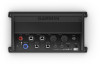
Connector View
POWER
Power cable connection
NETWORK
Garmin Marine Network
HDMI IN
HDMI
®
in
HDMI OUT
HDMI out to connect the chartplotter to a monitor.
Required for device functionality.
CVBS IN
Composite video in
Status LED
Power ground
Power button
NMEA 0183
NMEA
®
0183 and audio out
USB HOST
Touchscreen output for connecting a touchscreen monitor
USB OTG
Touchscreen input from a computer or other supported
USB accessory
NMEA 2000
NMEA 2000
®
network
J1939
J1939 network
Tools Needed
•
Drill
•
Drill bits appropriate for the surface and hardware (3.2 mm
(
1
/
8
in.) drill bit for included screws)
•
Phillips screwdriver
•
Pencil
Mounting Considerations
NOTICE
This device should be mounted in a location that is not exposed
to extreme temperatures or conditions. The temperature range
for this device is listed in the product specifications. Extended
exposure to temperatures exceeding the specified temperature
range, in storage or operating conditions, may cause device
failure. Extreme-temperature-induced damage and related
consequences are not covered by the warranty.
•
You must mount the device in a location where it will not be
submerged.
•
You must mount the device in a location with adequate
ventilation where it will not be exposed to extreme
temperatures.
•
You must mount the device at least 2.54 cm (1 in.) from
cables and other potential sources of interference.
•
You must mount the device in a location that allows room for
the routing and connection of all cables.
Mounting the GPSMAP 8700 Device
NOTICE
If you are mounting the device in fiberglass, when drilling the
pilot holes, it is recommended to use a countersink bit to drill a
clearance counterbore through only the top gel-coat layer. This
will help to avoid cracking in the gel-coat layer when the screws
are tightened.
NOTE:
Screws are included with the device, but they may not
be suitable for the mounting surface.
March 2019
190-02469-94_0A