Garmin GTX 32 Installation Manual
Garmin GTX 32 Manual
 |
View all Garmin GTX 32 manuals
Add to My Manuals
Save this manual to your list of manuals |
Garmin GTX 32 manual content summary:
- Garmin GTX 32 | Installation Manual - Page 1
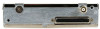
GTX 32 Transponder Installation Manual 190-00303-60 October, 2008 Revision F - Garmin GTX 32 | Installation Manual - Page 2
Telephone: 913.397.8200 Aviation Panel-Mount Technical Support Line (Toll Free) 1.888.606.5482 www.garmin.com Garmin (Europe) Ltd. Liberty House, Bulls Copse updated manual Added GDL 90 interconnect info Added caution regarding handle screw torque Page A Revision F GTX 32 Installation Manual 190- - Garmin GTX 32 | Installation Manual - Page 3
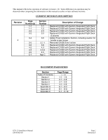
Replaced G1000 with Garmin Integrated Flight Deck DOCUMENT PAGINATION Section Table of Contents Section 1 Section 2 Section 3 Section 4 Appendix A Appendix B Appendix C Page Range i - vi 1-1 - 1-6 2-1 - 2-8 3-1 - 3-6 4-1 - 4-6 A-1 - A-2 B-1 - B-8 C-1 - C-10 GTX 32 Installation Manual 190-00303 - Garmin GTX 32 | Installation Manual - Page 4
required to be included on any and all reproductions in whole or in part of this manual. WARNING This product, its packaging, and its components contain chemicals known to the State , please refer to our web site at www.garmin.com/prop65. Page ii Revision F GTX 32 Installation Manual 190-00303-60 - Garmin GTX 32 | Installation Manual - Page 5
Continued Airworthiness ...3-6 4 SYSTEM INTERCONNECTS...4-1 4.1 Pin Function List...4-1 4.2 Power Function ...4-2 4.3 Altitude Functions ...4-2 4.4 Discrete Inputs/Outputs ...4-4 4.5 RS-232 Input/Output, Software Update Connections 4-5 GTX 32 Installation Manual 190-00303-60 Page iii Revision F - Garmin GTX 32 | Installation Manual - Page 6
PARAGRAPH PAGE APPENDIX A CONSTRUCTION AND VALIDATION OF STRUCTURES A.1 Static Test Loading ...A-1 A.2 Determining Static Load Capability A-1 APPENDIX B OUTLINE AND INSTALLATION DRAWINGS APPENDIX C INTERCONNECT DRAWINGS Page iv Revision F GTX 32 Installation Manual 190-00303-60 - Garmin GTX 32 | Installation Manual - Page 7
C-1 GTX 32 Typical Garmin Integrated Flight Deck System Interconnect Wiring Diagram C-1 C-2 GTX 32 to GNS 480 (CNX80) Interconnect Wiring Diagram C-3 C-3 GTX 32 to GDL 90, Typical Interconnect Wiring Diagram C-5 C-4 Dual GTX 32 Transponders, Single Altitude Encoder, Interconnect Wiring Diagram - Garmin GTX 32 | Installation Manual - Page 8
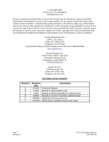
up-to-date bulletin and advisory information on the Garmin Dealer Resource web site at www.garmin.com using their Garmin -provided user name and password. MOD LEVEL SERVICE BULLETIN NUMBER SERVICE BULLETIN DATE PURPOSE OF MODIFICATION Page vi Revision F GTX 32 Installation Manual 190-00303-60 - Garmin GTX 32 | Installation Manual - Page 9
DESCRIPTION 1.1 Introduction This manual presents mechanical and electrical installation requirements for installing the Garmin GTX 32 Transponder as part of a Garmin Integrated Flight Deck. The GTX 32 can also be incorporated as a remote mounted unit in installations with other compatible control - Garmin GTX 32 | Installation Manual - Page 10
the aircraft's existing equipment. This GTX 32 installation manual identifies an installation to include: • GTX 32 Transponder • Transponder Antenna • Control and Display unit • An Altitude Encoder The STC includes all the data needed to support the installation of the GTX 32 in all the aircraft - Garmin GTX 32 | Installation Manual - Page 11
1.6 Technical Specifications It is the responsibility of the installing agency to obtain the latest revision of the GTX 32 Environmental Qualification Form. This form is available directly from Garmin under the following part number: GTX 32 Environmental Qualification Form, Garmin part number 005- - Garmin GTX 32 | Installation Manual - Page 12
fax-on-demand service to provide forms by fax. The GTX 32 owner accepts all responsibility for obtaining the proper licensing before using the GTX 32. CAUTION The Garmin could invalidate the license and make it unlawful to operate the equipment. Page 1-4 Revision F GTX 32 Installation Manual 190 - Garmin GTX 32 | Installation Manual - Page 13
materials along with this manual. Part Number 190-00303-00 190-00303-04 560-0982-01 560-1049-02 Document G1000 System Installation Manual G1000 Line Maintenance and Configuration Manual GNS 480 (CNX80) Installation Manual GDL 90 Installation Manual GTX 32 Installation Manual 190-00303-60 Page - Garmin GTX 32 | Installation Manual - Page 14
East 151st Street Olathe, Kansas 66062, U.S.A. Phone: 913/397.8200 FAX: 913/397.8282 Garmin (Europe) Ltd. Liberty House, Bulls Copse Road Hounsdown Business Park Southampton, SO40 9RB, U.K. Phone: +44/0870.851241 FAX: +44/0870.851251 Page 1-6 Revision F GTX 32 Installation Manual 190-00303-60 - Garmin GTX 32 | Installation Manual - Page 15
Block) Backplate Assembly, GTX 32 011-00677-01 Garmin Transponder Antenna kit* 010-10160-00 *Note: A transponder antenna approved to TSO C66( ) or C74( ) that has been installed to meet the requirements of this manual may be used with the GTX 32. GTX 32 Installation Manual 190-00303-60 Page - Garmin GTX 32 | Installation Manual - Page 16
(CNX80) installation. Use encoding altimeter manufacturer's instructions. The Garmin GAE 43 (Garmin P/N 013-00066-00) can provide altitude data in either serial or parallel gray code format. 2.3 Installation Considerations When installed as part of a Garmin Integrated Flight Deck system, the GTX 32 - Garmin GTX 32 | Installation Manual - Page 17
plane material must be added. Conductive wire mesh, radials, or thin aluminum sheets embedded in the composite material provide the proper ground plane allowing the antenna pattern (gain) to be maximized for optimum transponder performance. GTX 32 Installation Manual 190-00303-60 Page 2-3 Revision - Garmin GTX 32 | Installation Manual - Page 18
wire such as AWG #18 or #16 may be needed for power connections. If using used for specific lengths of cable. Any cable meeting specifications is acceptable for the installation Franklin Drive Franklin, WI 53132 Tel: 800-327-9473 414-421-5300 Fax: 414-421-5301 GTX 32 Installation Manual 190-00303-60 - Garmin GTX 32 | Installation Manual - Page 19
pressurized aircraft is beyond the scope of the GTX 32 STC. Additional manufacturer's data may be necessary and FAA approval may be required to cover the installation of the antenna. 2.6 Cooling Air Refer to the G1000 System Installation manual, Garmin part number 190-00303-00, for information on - Garmin GTX 32 | Installation Manual - Page 20
orientation. After the cable assemblies are made and wiring installed to the rack back plate, route wiring bundle as appropriate. Use cable ties to secure the cable assemblies and coax to provide strain relief for the cable assemblies. Page 2-6 Revision F GTX 32 Installation Manual 190-00303-60 - Garmin GTX 32 | Installation Manual - Page 21
the remote rack (P/N 115-00628-00) for use in a stand-alone installation. The installer must provide any additional mounting hardware required for the remote stand-alone rack. Figure 2-3. GTX 32 Remote Stand-Alone Rack (115-00628-00) GTX 32 Installation Manual 190-00303-60 Page 2-7 Revision F - Garmin GTX 32 | Installation Manual - Page 22
Figure 2-4. GTX 32 Remote Stand-Alone Rack, Suggested Mounting Locations Page 2-8 Revision F GTX 32 Installation Manual 190-00303-60 - Garmin GTX 32 | Installation Manual - Page 23
wiring diagrams. Construct the actual harnesses in accordance with the aircraft manufacturer authorized interconnect standards. CAUTION Check wiring connections for errors before inserting the GTX 32 into the rack. Incorrect wiring could cause internal component damage. Manufacturer Garmin - Garmin GTX 32 | Installation Manual - Page 24
G1000 System Installation Manual (190-00303-00), as well as the SPIDER Installation Instructions (190-00313-02) and Shield Block Installation Instructions (190-00313-09). Non- Garmin Integrated Flight Deck Installations: GTX 32 installations that are not installed with the Garmin Integrated Flight - Garmin GTX 32 | Installation Manual - Page 25
, removed or relocated along with the date accomplished. Include your name and certificate number in the aircraft records. Section 1.6.1 identifies the weight of the new GTX 32 equipment, Figure B-1 shows the center of gravity. GTX 32 Installation Manual 190-00303-60 Page 3-3 Revision F - Garmin GTX 32 | Installation Manual - Page 26
. Use the following values for Power Loads computation: GTX 32 Input GTX 32 Main Power Table 3-3. Unit Power Loads 1 14 VDC 2 Typical Max. 28 VDC Typical Max. 1.1 A 1.85 A 0.6 A 0.9 A 3.5.1 Circuit Breaker Placard Install a Circuit Breaker Placard labeled Transponder or Transponder - Garmin GTX 32 | Installation Manual - Page 27
3.7.1 Configuration When installed as part of a Garmin Integrated Flight Deck, the GTX 32 transponder must have FAA approved configuration data. Configuration data is loaded to the GTX 32 from an aircraft-specific SW Loader Card. Transponder settings are predetermined for a specific aircraft and are - Garmin GTX 32 | Installation Manual - Page 28
appropriate regulations. The test is typically done as a ramp test using a transponder ramp test set, such as the IFR ATC-600A or TIC GTX 32 is 'on condition' only. Aircraft covered under the GTX 32 STC AML should use ICA document number 190-00303-63. Page 3-6 Revision F GTX 32 Installation Manual - Garmin GTX 32 | Installation Manual - Page 29
UPLOAD) -- 22 AIRBORNE SENSE (SQUAT SWITCH) In 23 AIRCRAFT POWER 2 In 24 RS-232 OUT 2 Out 25 SIGNAL GROUND -- * Denotes Active Low (Ground to activate). GTX 32 Installation Manual 190-00303-60 Page 4-1 Revision F - Garmin GTX 32 | Installation Manual - Page 30
wiring connections. When connecting two GTX 32 transponders to a GPS, the unit can only receive RS-232 serial data from one unit at a time. Use a DPDT switch to connect both serial data and External Standby Select. Refer to Figure C-4 Sheets 1 and 2. Page 4-2 Revision F GTX 32 Installation Manual - Garmin GTX 32 | Installation Manual - Page 31
RS-232 data from GNS 480 (CNX80) or Garmin Integrated Flight Deck system 2) RS-232 Fuel/Air Data Computer (if configured W/ALT.) 3) Parallel wire Gray Code input 4) Shadin Altitude Serializer/Encoder 5) Icarus Altitude Serializer/Encoder GTX 32 Installation Manual 190-00303-60 Page 4-3 Revision F - Garmin GTX 32 | Installation Manual - Page 32
* (remote STBY) is an ON or OFF input used typically for dual transponder installations. When grounded, the GTX 32 is placed in standby. EXTERNAL SUPPRESSION should be connected if a DME is installed in the aircraft avionics system. The GTX 32 suppression I/O pulses may not be compatible with all - Garmin GTX 32 | Installation Manual - Page 33
Output, Software Update Connections When the GTX 32 is installed in a system other than a Garmin Integrated Flight Deck system an optional RS-232 serial data connector should be installed in the aircraft for future software upgrades, negating the need to remove the transponder from the aircraft. The - Garmin GTX 32 | Installation Manual - Page 34
This page intentionally left blank Page 4-6 Revision F GTX 32 Installation Manual 190-00303-60 - Garmin GTX 32 | Installation Manual - Page 35
is capable of supporting the required loads. The GTX 32 installation must be capable of use a calibrated force gauge at the location of the center of gravity when the unit is mounted. 4. Verify there is no damage or permanent deformation of the structure after 3 seconds. GTX 32 Installation Manual - Garmin GTX 32 | Installation Manual - Page 36
line, braided wire, or other 61.2 lb. forward). 7. Examine the support structure carefully. If there has been damage or GTX 32 equipment rack may be permanently mounted on it. Figure A-1. Upward Static Load Test Figure A-2. Forward Static Load Test Page A-2 Revision F GTX 32 Installation Manual - Garmin GTX 32 | Installation Manual - Page 37
PLACES .39 9.78 .48 12.19 TYP .37 9.27 7.26 184.5 8.03 203.9 8.77 222.8 9.11 231.3 .377 9.58 TYP 3.727 94.67 TYP GTX 32 Installation Manual 190-00303-60 P3271 4.75 120.7 3.18 80.8 FORCED-AIR COOLING PORT 1.710 43.43 NOTES: 1. DIMENSIONS: 2. TOLERANCES: INCHES[mm] INCH .X ±0.1 .XX ±0.04 .XXX - Garmin GTX 32 | Installation Manual - Page 38
32 x .375 100 FLAT HEAD 12 PLACES 1 211-60234-06 4 #4-40 X .187 PAN HEAD PHILLIPS 4 PLACES GTX 32 Installation Manual 190-00303-60 011-00768-00 GTX 32 BE USED IN EACH NUT PLATE POSITION. 4. APPLY THREAD LOCKING COMPOUND TO THREADED FASTENERS IF PRE-APPLIED PATCH IS DAMAGED Figure B-2. GTX 32 G1000 - Garmin GTX 32 | Installation Manual - Page 39
DRAWINGS 211-60234-06 4 PLACES 1 125-00032-04 1 211-63234-12 2 PLACES 2 232-00013-01 1 212-20014-00 1 234-10002-00 1 GTX 32 Installation Manual 190-00303-60 GROUNDING WIRES 011-00980-01 2 011-00950-02 2 330-00184-25 336-00022-00 336-00023-00 AS NEEDED 2 330-00326-00 1 NOTES: 1. PART OF 011 - Garmin GTX 32 | Installation Manual - Page 40
APPENDIX B OUTLINE AND INSTALLATION DRAWINGS 4.25 [108.0] 1.69 [42.9] GTX 32 Installation Manual 190-00303-60 6.84 [173.9] 3.30 [83.7] 5.27 [133.8] 3.70 [93.9] 1.05 [26.6] 0.32 [8.2] 1.67 [42.3] 8.01 [203.5] 8.77 [222.7] 4.75 [120.6] 4X Ø0.18 [Ø4.6] Figure B-3. GTX 32 Remote Mounted Stand- - Garmin GTX 32 | Installation Manual - Page 41
APPENDIX C INTERCONNECT DRAWINGS GTX 32 Installation Manual 190-00303-60 Figure C-1. GTX 32 Typical Garmin Integrated Flight Deck System Interconnect Wiring Diagram Page C-1 (Page C-2 blank) Revision F - Garmin GTX 32 | Installation Manual - Page 42
APPENDIX C INTERCONNECT DRAWINGS GTX 32 Installation Manual 190-00303-60 Figure C-2. GTX 32 to GNS 480 (CNX80) Interconnect Wiring Diagram Page C-3 (Page C-4 blank) Revision F - Garmin GTX 32 | Installation Manual - Page 43
APPENDIX C INTERCONNECT DRAWINGS P1 P2 P2 CH2 CH6 CH7 GDL 90 12 33 15 RS232 RxD 5 24 7 GND 8. THE GTX 32 WILL REMOTELY CONTROL THE GDL 90 DATALINK. 9. GTX 32 Installation Manual 190-00303-60 Figure C-3. GTX 32 to GDL 90, Typical Interconnect Wiring Diagram Page C-5 (Page C-6 blank) Revision F - Garmin GTX 32 | Installation Manual - Page 44
APPENDIX C INTERCONNECT DRAWINGS GTX 32 Installation Manual 190-00303-60 Figure C-4. Dual GTX 32 Transponders, Single Altitude Encoder, Interconnect Wiring Diagram (Sheet 1 of 2) Page C-7 (Page C-8 blank) Revision F - Garmin GTX 32 | Installation Manual - Page 45
APPENDIX C INTERCONNECT DRAWINGS GTX 32 Installation Manual 190-00303-60 Figure C-4. Dual GTX 32 Transponders, Single Altitude Encoder, Interconnect Wiring Diagram (Sheet 2) Page C-9 (Page C-10 blank) Revision F
-
 1
1 -
 2
2 -
 3
3 -
 4
4 -
 5
5 -
 6
6 -
 7
7 -
8
-
9
-
10
-
11
-
12
-
13
-
14
-
15
-
16
-
17
-
18
-
19
-
20
-
21
-
22
-
23
-
24
-
25
-
26
-
27
-
28
-
29
-
30
-
31
-
32
-
33
-
34
-
35
-
36
-
37
-
38
-
39
-
40
-
41
-
42
-
43
-
44
-
45
 |
 |

190-00303-60
October, 2008
Revision F
GTX 32
Transponder
Installation Manual