Gateway MT6460 8511725 - Gateway Service Guide
Gateway MT6460 Manual
 |
View all Gateway MT6460 manuals
Add to My Manuals
Save this manual to your list of manuals |
Gateway MT6460 manual content summary:
- Gateway MT6460 | 8511725 - Gateway Service Guide - Page 1
GATEWAY NOTEBOOK SERVICEGUIDE ® - Gateway MT6460 | 8511725 - Gateway Service Guide - Page 2
- Gateway MT6460 | 8511725 - Gateway Service Guide - Page 3
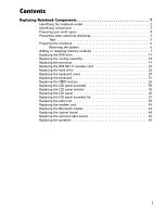
the notebook 6 Removing the battery 6 Adding or replacing memory modules 7 Replacing the DVD drive 11 Replacing the cooling assembly 14 Replacing the processor 19 Replacing the IEEE 802.11 wireless card 22 Replacing the hard drive 26 Replacing the keyboard cover 29 Replacing the keyboard - Gateway MT6460 | 8511725 - Gateway Service Guide - Page 4
Contents ii - Gateway MT6460 | 8511725 - Gateway Service Guide - Page 5
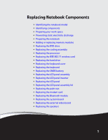
the notebook • Adding or replacing memory modules • Replacing the DVD drive • Replacing the cooling assembly • Replacing the processor • Replacing the IEEE 802.11 wireless card • Replacing the hard drive • Replacing the keyboard cover • Replacing the keyboard • Replacing the CMOS battery • Replacing - Gateway MT6460 | 8511725 - Gateway Service Guide - Page 6
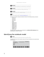
service guide for the notebook. Failure to follow the approved tasks for the notebook model may result in damage to the notebook. The label on the bottom of the notebook contains information that identifies the notebook model and its features. Online Support: Tech Support Phone: Hours: Model - Gateway MT6460 | 8511725 - Gateway Service Guide - Page 7
www.gateway.com Identifying components Use this chart to identify the main components of the notebook. For a complete list of replaceable parts, see "Contents" on page i. LCD panel assembly (see page 38) Keyboard cover (see page 29) Keyboard (see page 31) Cooling assembly (see page 11) Processor ( - Gateway MT6460 | 8511725 - Gateway Service Guide - Page 8
Replacing Notebook Components Preparing your work space Before performing maintenance on the notebook, make sure that your work space and the notebook the following: • Place each component's screws in their own section of a parts sorter. • Place each component's screws next to the component on your - Gateway MT6460 | 8511725 - Gateway Service Guide - Page 9
in this guide involve removing tape that holds cables or components. Two types of tape are used in this Gateway notebook: • Mylar, non-conductive tape is typically transparent, with a red or brown tint. • Conductive tape is typically grey or silver. If the existing tape cannot be reused, replace it - Gateway MT6460 | 8511725 - Gateway Service Guide - Page 10
before opening the case. Replace the cover before you restore power or reconnect the modem and network cables. To prepare the notebook for maintenance: 1 Make sure that the DVD drive does not contain a disc. 2 Disconnect all peripheral devices and remove any PC Cards and memory cards. 3 Turn off the - Gateway MT6460 | 8511725 - Gateway Service Guide - Page 11
.com Adding or replacing memory modules Important Use only memory modules designed for this Gateway notebook. Tools you need to complete this task: Phillips #0 screwdriver Screws removed during this task: 1 black (keyboard) Memory bay To add or replace memory modules: 1 Complete the steps in - Gateway MT6460 | 8511725 - Gateway Service Guide - Page 12
Replacing Notebook Components 2 Remove the keyboard screw. Tip The screw hole is marked with a K. Keyboard screw 3 Loosen the six memory bay cover screws (these screws cannot be removed). Tip Depending on your model, not all screws may be captive. Screws Screws 8 - Gateway MT6460 | 8511725 - Gateway Service Guide - Page 13
www.gateway.com 4 Use the thumb notch to lift the memory bay cover, then remove it. Be careful not to break off the tabs located on the end of the cover opposite of the thumb notch. - Gateway MT6460 | 8511725 - Gateway Service Guide - Page 14
Replacing Notebook Components 6 Pull the memory module out of the slot. 7 Hold the new or replacement module at a 30-degree angle and press it into the empty memory in the memory bay. 8 Replace the memory bay cover, then tighten the cover screws. 9 Replace the keyboard screw. Tip The screw hole is marked - Gateway MT6460 | 8511725 - Gateway Service Guide - Page 15
www.gateway.com Replacing the DVD drive Tools you need to complete this task: Phillips #0 screwdriver Screws removed during this task: 1 black (keyboard) 1 black (DVD drive) To replace the DVD drive: 1 Complete the steps in "Preparing the notebook" on page 6. 2 Remove the keyboard screw. Tip The - Gateway MT6460 | 8511725 - Gateway Service Guide - Page 16
Replacing Notebook Components 3 Loosen the six memory bay cover screws (these screws cannot be removed). Tip Depending on your model, not all screws may be captive. Screws Screws 4 Use the thumb notch to lift the memory bay cover, then remove it. Be careful not to break off the tabs located on the - Gateway MT6460 | 8511725 - Gateway Service Guide - Page 17
bracket. DVD bracket 7 Slide the new DVD drive into the drive bay. Make sure that the drive fits securely in the bay. 8 Secure the DVD drive with the screw removed in Step 5. 9 Replace the memory bay cover, then tighten the cover screws. 10 Replace the keyboard screw. Tip The screw hole is marked - Gateway MT6460 | 8511725 - Gateway Service Guide - Page 18
Additional materials you may need to complete this task: • X-23-7762 thermal grease Screws removed during this task: 1 black (keyboard) To replace the cooling assembly: 1 Complete the steps in "Preparing the notebook" on page 6. 2 Remove the keyboard screw. Tip The screw hole is marked with - Gateway MT6460 | 8511725 - Gateway Service Guide - Page 19
www.gateway.com 3 Loosen the six memory bay cover screws (these screws cannot be removed). Tip Depending on your model, not all screws may be captive. Screws Screws 4 Use the thumb notch to lift the memory bay cover, then remove it. Be careful not to break off the tabs located on the end of the - Gateway MT6460 | 8511725 - Gateway Service Guide - Page 20
Replacing Notebook Components 5 Loosen the three or four screws (these screws cannot be removed) that secure the cooling assembly to the system board. Use the numbers stamped in the metal next . Important The number of screws varies by model. Screw Screw Screw -OR- Screw Screw Screw Screw 16 - Gateway MT6460 | 8511725 - Gateway Service Guide - Page 21
.gateway.com 6 .At the same time as you lift, move the cooling assembly away from the side of the notebook, then remove it. The cooling assembly cable is attached to the system board at this point. Be careful not to break the cable. Caution The cooling assembly cable is attached to the system board - Gateway MT6460 | 8511725 - Gateway Service Guide - Page 22
Replacing Notebook Components 12 Tighten the three or four screws, in numerical order, in the them in numerical order. Important The number of screws varies by model. 13 Replace the memory bay cover, then tighten the cover screws. 14 Replace the keyboard screw. Tip The screw hole is marked with a K. - Gateway MT6460 | 8511725 - Gateway Service Guide - Page 23
to complete this task: • X-23-7762 thermal grease Screws removed during this task: 1 black (keyboard) To replace the processor: 1 Complete the steps in "Preparing the notebook" on page 6. 2 Remove the cooling assembly by following the instructions in "Replacing the cooling assembly" on page 14. 19 - Gateway MT6460 | 8511725 - Gateway Service Guide - Page 24
Replacing Notebook Components 3 Use a flat-blade screwdriver to turn the processor lock screw ¼-turn counter-clockwise. -ORUse a flat-blade screwdriver to turn the processor lock screw ½-turn counter-clockwise. You will hear a click when the processor lock is unlocked. 20 - Gateway MT6460 | 8511725 - Gateway Service Guide - Page 25
, remove any thermal grease residue from the cooling assembly using a soft cloth and isopropyl alcohol. 7 Place new thermal grease on the processor. Use only enough to cover the CPU die. 8 Replace the cooling assembly by following the instructions in "Replacing the cooling assembly" on page 14. 21 - Gateway MT6460 | 8511725 - Gateway Service Guide - Page 26
in place during any and all operation of the notebook's wireless feature. Tools you need to complete this task: Phillips #0 screwdriver Screws removed during this task: 1 black (wireless card) Select models only Wireless bay To replace the 802.11 wireless card: 1 Complete the steps in "Preparing the - Gateway MT6460 | 8511725 - Gateway Service Guide - Page 27
www.gateway.com 2 Loosen the wireless bay cover screw (this screw cannot be removed), then remove the wireless bay cover. Screw 3 Unplug the two antenna cables. 4 Move the antenna cables out of the way. 23 - Gateway MT6460 | 8511725 - Gateway Service Guide - Page 28
Replacing Notebook Components 5 If the wireless card is held by clips, press outward on the clip at each side of the card until the card tilts up. -ORIf the wireless card is held by a screw, remove the screw. Screw 24 - Gateway MT6460 | 8511725 - Gateway Service Guide - Page 29
www.gateway.com 6 Pull the old card out of the slot. 7 Hold the new card at antenna cables out of the way. 9 If the wireless card is held by clips, press the card down until it clicks into place. -ORIf the wireless card is held by a screw, replace the screw. 10 Reattach the light gray antenna cable - Gateway MT6460 | 8511725 - Gateway Service Guide - Page 30
Replacing Notebook Components Replacing the hard drive Tools you need to complete this task: Phillips #0 screwdriver Screws removed during this task: 2 black (hard drive kit) 4 chrome (hard drive cover) Hard drive kit To replace the hard drive: 1 Complete the steps in "Preparing the notebook" on - Gateway MT6460 | 8511725 - Gateway Service Guide - Page 31
www.gateway.com 3 Slide the old hard drive kit out of the notebook. 4 If the hard drive shipped to you already attached to a new cover, go to Step 8. -OR- If the hard drive shipped to you without a new cover, remove the four screws that secure the hard drive to the hard drive bay cover. Screws - Gateway MT6460 | 8511725 - Gateway Service Guide - Page 32
Replacing Notebook Components 5 Remove the cover from the old drive. 6 Place the new drive, label side up, onto the cover so the screw holes line up. 7 Replace the screws that secure the cover to the drive. 8 Slide the new hard drive kit into the notebook, then replace the kit screws. 28 - Gateway MT6460 | 8511725 - Gateway Service Guide - Page 33
.gateway.com Replacing the keyboard cover Tools you need to complete this task: Flat-blade driver - OR - Phillips #0 screwdriver Screws removed during this task: Scribe or non-marring tool 2 black (keyboard cover) To replace the keyboard cover: 1 Complete the steps in "Preparing the notebook - Gateway MT6460 | 8511725 - Gateway Service Guide - Page 34
cover off the notebook. You will hear small snapping sounds as the cover comes away from the notebook. 8 Place the new cover on the notebook, then press down all the way across. Caution If the cover is not correctly replaced, the notebook could be damaged when you try to close the LCD panel. 9 - Gateway MT6460 | 8511725 - Gateway Service Guide - Page 35
-blade driver - OR - Phillips #0 screwdriver Screws removed during this task: Scribe or non-marring tool 2 black (keyboard cover) 1-3 black (keyboard) To replace the keyboard: 1 Complete the steps in "Preparing the notebook" on page 6. 2 Remove the keyboard cover by following the instructions - Gateway MT6460 | 8511725 - Gateway Service Guide - Page 36
Replacing Notebook Components 5 Close the LCD panel, turn the notebook over so the bottom is facing up, then loosen the six memory bay cover screws (these screws cannot be removed). Tip Depending on your model, not all screws may be captive. Screws Screws 6 Use the thumb notch to lift the memory bay - Gateway MT6460 | 8511725 - Gateway Service Guide - Page 37
www.gateway.com 7 Loosen the wireless bay cover screw (this screw cannot be removed), then remove the wireless bay cover. Screw 8 Remove the two optional keyboard screws. Tip Depending on the keyboard features, one or both of these screws may be absent. Screw Screw 9 Turn the notebook over so the - Gateway MT6460 | 8511725 - Gateway Service Guide - Page 38
Replacing Notebook Components 11 Carefully rotate the keyboard toward you so it lies keys-down on top of the notebook. Be careful not to damage the LCD panel. 12 Lift the black keyboard connector clip, then remove the cable. Be careful not to touch or damage any other components. Keyboard connector - Gateway MT6460 | 8511725 - Gateway Service Guide - Page 39
cover by following the instructions in "Replacing the keyboard cover" on page 29. 20 Turn the notebook over so the bottom is facing up, then replace the keyboard screws removed in Step 8. 21 Replace the memory bay cover and wireless network bay cover. 22 Replace the keyboard screw removed in Step - Gateway MT6460 | 8511725 - Gateway Service Guide - Page 40
by following the instructions in "Replacing the keyboard cover" on page 29. 3 Open the keyboard compartment by following the instructions in "Replacing the keyboard" on page 31. Tip You do not need to unplug the keyboard from the notebook. 4 Locate the old battery on the system board. If you have - Gateway MT6460 | 8511725 - Gateway Service Guide - Page 41
any other components. 6 Plug the new battery into the system board. Important Use only CMOS batteries designed for this Gateway notebook. The non-conductive sleeve and wires are not reusable. 7 Replace the palm rest (if removed) by following the instructions in "Replacing the palm rest" on page 56 - Gateway MT6460 | 8511725 - Gateway Service Guide - Page 42
802.11 wireless card" on page 22. 3 Remove the keyboard cover by following the instructions in "Replacing the keyboard cover" on page 29. 4 Open the keyboard compartment by following the instructions in "Replacing the keyboard" on page 31. Tip You do not need to unplug the keyboard from the notebook - Gateway MT6460 | 8511725 - Gateway Service Guide - Page 43
slightly, then slide the video cable out from under the clips. 7 Taking care to note the cables' routing and positions as they are installed from Gateway, pull the antenna wires out from under the system board, then slide the wires out from under the retaining clips. 39 - Gateway MT6460 | 8511725 - Gateway Service Guide - Page 44
8 Remove the four hinge screws that secure the LCD panel to the notebook. Screws 9 Lift the LCD panel assembly away from the notebook. The LCD panel assembly is now completely detached from the notebook. 10 Place the new LCD panel assembly onto the notebook, then replace the four hinge screws. 40 - Gateway MT6460 | 8511725 - Gateway Service Guide - Page 45
the system board, then into the wireless card area. 12 Slide the LCD video cable under the retaining clips, then plug the LCD video connector into the notebook. 13 Close the keyboard compartment by following the instructions in "Replacing the keyboard" on page 31. 14 Replace the keyboard cover by - Gateway MT6460 | 8511725 - Gateway Service Guide - Page 46
802.11 wireless card" on page 22. 3 Remove the keyboard cover by following the instructions in "Replacing the keyboard cover" on page 29. 4 Open the keyboard compartment by following the instructions in "Replacing the keyboard" on page 31. Tip You do not need to unplug the keyboard from the notebook - Gateway MT6460 | 8511725 - Gateway Service Guide - Page 47
www.gateway.com 6 Remove the four or six rubber inserts from the front of the LCD panel assembly. Rubber insert Rubber insert Rubber insert Rubber insert Rubber insert Rubber insert 7 Remove the four or six screws from the front of the LCD panel assembly. Tip On select models, you may be able - Gateway MT6460 | 8511725 - Gateway Service Guide - Page 48
Replacing Notebook Components 8 Carefully separate the front and back of the LCD panel assembly. Tip If you only removed the bottom two screws in the previous step, - Gateway MT6460 | 8511725 - Gateway Service Guide - Page 49
Close the keyboard compartment by following the instructions in "Replacing the keyboard" on page 31. 19 Replace the keyboard cover by following the instructions in "Replacing the keyboard cover" on page 29. 20 Plug the antenna cables into the IEEE 802.11 wireless card, then replace the wireless bay - Gateway MT6460 | 8511725 - Gateway Service Guide - Page 50
802.11 wireless card" on page 22. 3 Remove the keyboard cover by following the instructions in "Replacing the keyboard cover" on page 29. 4 Open the keyboard compartment by following the instructions in "Replacing the keyboard" on page 31. Tip You do not need to unplug the keyboard from the notebook - Gateway MT6460 | 8511725 - Gateway Service Guide - Page 51
www.gateway.com 6 Remove the four or six rubber inserts from the front of the LCD panel assembly. Rubber insert Rubber insert Rubber insert Rubber insert Rubber - Gateway MT6460 | 8511725 - Gateway Service Guide - Page 52
Replacing Notebook Components 8 Carefully separate the front and back of the LCD panel assembly. 9 Remove the two screws holding the bracket to the LCD panel assembly, then remove the bracket. Screw Screw 48 - Gateway MT6460 | 8511725 - Gateway Service Guide - Page 53
www.gateway.com 10 Remove the four screws connecting the LCD panel to the LCD panel assembly. Screw Screw 11 Remove the LCD panel from the LCD panel assembly. Screw Screw 49 - Gateway MT6460 | 8511725 - Gateway Service Guide - Page 54
Close the keyboard compartment by following the instructions in "Replacing the keyboard" on page 31. 21 Replace the keyboard cover by following the instructions in "Replacing the keyboard cover" on page 29. 22 Plug the antenna cables into the IEEE 802.11 wireless card, then replace the wireless bay - Gateway MT6460 | 8511725 - Gateway Service Guide - Page 55
802.11 wireless card" on page 22. 3 Remove the keyboard cover by following the instructions in "Replacing the keyboard cover" on page 29. 4 Open the keyboard compartment by following the instructions in "Replacing the keyboard" on page 31. Tip You do not need to unplug the keyboard from the notebook - Gateway MT6460 | 8511725 - Gateway Service Guide - Page 56
Replacing Notebook Components 6 Remove the four or six rubber inserts from the front of the LCD panel assembly. Rubber insert Rubber insert Rubber insert Rubber insert Rubber - Gateway MT6460 | 8511725 - Gateway Service Guide - Page 57
www.gateway.com 8 Carefully separate the front and back of the LCD panel assembly. 9 Remove the two screws holding the bracket to the LCD panel assembly, then remove the bracket. Screw Screw 53 - Gateway MT6460 | 8511725 - Gateway Service Guide - Page 58
Replacing Notebook Components 10 Remove the four screws connecting the LCD panel to the LCD panel assembly. Screw Screw 11 Remove the LCD panel from the LCD panel assembly. Screw Screw 12 Place the LCD panel into the new LCD panel assembly lid. 13 Replace the four screws removed in Step 10. 14 - Gateway MT6460 | 8511725 - Gateway Service Guide - Page 59
Close the keyboard compartment by following the instructions in "Replacing the keyboard" on page 31. 20 Replace the keyboard cover by following the instructions in "Replacing the keyboard cover" on page 29. 21 Plug the antenna cables into the IEEE 802.11 wireless card, then replace the wireless bay - Gateway MT6460 | 8511725 - Gateway Service Guide - Page 60
card by following the instructions in "Replacing the IEEE 802.11 wireless card" on page 22. 4 Remove the hard drive kit by following the instructions in "Replacing the hard drive" on page 26. 5 Remove the keyboard cover by following the instructions in "Replacing the keyboard cover" on page 29 - Gateway MT6460 | 8511725 - Gateway Service Guide - Page 61
www.gateway.com 8 Lift the black touchpad connector clip, then remove the touchpad cable. Be careful not to touch or damage any other components. 9 Remove the four screws from the top of the palm rest. Screws 57 - Gateway MT6460 | 8511725 - Gateway Service Guide - Page 62
in "Replacing the keyboard cover" on page 29. 17 Replace the hard drive kit by following the instructions in "Replacing the hard drive" on page 26. 18 Replace the DVD drive by following the instructions in "Replacing the DVD drive" on page 11. 19 Plug the antenna cables into the IEEE 802.11 wireless - Gateway MT6460 | 8511725 - Gateway Service Guide - Page 63
card by following the instructions in "Replacing the IEEE 802.11 wireless card" on page 22. 4 Remove the hard drive kit by following the instructions in "Replacing the hard drive" on page 26. 5 Remove the keyboard cover by following the instructions in "Replacing the keyboard cover" on page 29 - Gateway MT6460 | 8511725 - Gateway Service Guide - Page 64
Replacing Notebook Components 7 Remove the LCD panel by following the instructions in "Replacing the LCD panel assembly" on page 38. 8 Remove the palm rest by following the instructions in "Replacing the palm rest" on page 56. 9 Remove the two screws that secure the modem card to the system board. - Gateway MT6460 | 8511725 - Gateway Service Guide - Page 65
in "Replacing the keyboard cover" on page 29. 17 Replace the hard drive kit by following the instructions in "Replacing the hard drive" on page 26. 18 Replace the DVD drive by following the instructions in "Replacing the DVD drive" on page 11. 19 Plug the antenna cables into the IEEE 802.11 wireless - Gateway MT6460 | 8511725 - Gateway Service Guide - Page 66
card by following the instructions in "Replacing the IEEE 802.11 wireless card" on page 22. 4 Remove the hard drive kit by following the instructions in "Replacing the hard drive" on page 26. 5 Remove the keyboard cover by following the instructions in "Replacing the keyboard cover" on page 29 - Gateway MT6460 | 8511725 - Gateway Service Guide - Page 67
in "Replacing the keyboard cover" on page 29. 16 Replace the hard drive kit by following the instructions in "Replacing the hard drive" on page 26. 17 Replace the DVD drive by following the instructions in "Replacing the DVD drive" on page 11. 18 Plug the antenna cables into the IEEE 802.11 wireless - Gateway MT6460 | 8511725 - Gateway Service Guide - Page 68
drive) 2 black (hard drive kit) 1 black (wireless card) Select models only 2 black (keyboard cover) 1-3 black (keyboard) 4 black (LCD panel hinges) 4 black (palm rest - top) 17 black (palm rest - bottom) 2 chrome (modem) Select models only 4 black (system board) To replace the system board - Gateway MT6460 | 8511725 - Gateway Service Guide - Page 69
processor" on page 19. 6 If the notebook has IEEE 802.11 wireless networking built in, remove the IEEE 802.11 wireless card from the old system board and install it on the new system board by following the instructions in "Replacing the IEEE 802.11 wireless card" on page 22. 7 Remove the hard drive - Gateway MT6460 | 8511725 - Gateway Service Guide - Page 70
in "Replacing the keyboard cover" on page 29. 22 Replace the hard drive kit by following the instructions in "Replacing the hard drive" on page 26. 23 Replace the DVD drive by following the instructions in "Replacing the DVD drive" on page 11. 24 Plug the antenna cables into the IEEE 802.11 wireless - Gateway MT6460 | 8511725 - Gateway Service Guide - Page 71
www.gateway.com Replacing the external video board Tools you need to complete this task: Flat-blade driver - OR - Scribe or non-marring tool Phillips #0 screwdriver Screws removed during this task: 5.0 mm hex nutdriver 1 black (DVD drive) 2 black (hard drive kit) 2 black (keyboard cover) - Gateway MT6460 | 8511725 - Gateway Service Guide - Page 72
in "Replacing the keyboard cover" on page 29. 18 Replace the hard drive kit by following the instructions in "Replacing the hard drive" on page 26. 19 Replace the DVD drive by following the instructions in "Replacing the DVD drive" on page 11. 20 Plug the antenna cables into the IEEE 802.11 wireless - Gateway MT6460 | 8511725 - Gateway Service Guide - Page 73
card by following the instructions in "Replacing the IEEE 802.11 wireless card" on page 22. 5 Remove the hard drive kit by following the instructions in "Replacing the hard drive" on page 26. 6 Remove the keyboard cover by following the instructions in "Replacing the keyboard cover" on page 29 - Gateway MT6460 | 8511725 - Gateway Service Guide - Page 74
in "Replacing the keyboard cover" on page 29. 19 Replace the hard drive kit by following the instructions in "Replacing the hard drive" on page 26. 20 Replace the DVD drive by following the instructions in "Replacing the DVD drive" on page 11. 21 Plug the antenna cables into the IEEE 802.11 wireless - Gateway MT6460 | 8511725 - Gateway Service Guide - Page 75
.com Copyright © 2006 Gateway, Inc. All rights reserved. Gateway, Gateway Country, the Gateway stylized logo, and the black-and-white spot design are trademarks or registered trademarks of Gateway, Inc. in the United States and other countries. All other brands and product names are trademarks - Gateway MT6460 | 8511725 - Gateway Service Guide - Page 76
Replacing Notebook Components 72 - Gateway MT6460 | 8511725 - Gateway Service Guide - Page 77
- Gateway MT6460 | 8511725 - Gateway Service Guide - Page 78
MAN BLADE/OAS SVC GDE R3 12/06
-
 1
1 -
 2
2 -
 3
3 -
 4
4 -
 5
5 -
 6
6 -
 7
7 -
8
-
9
-
10
-
11
-
12
-
13
-
14
-
15
-
16
-
17
-
18
-
19
-
20
-
21
-
22
-
23
-
24
-
25
-
26
-
27
-
28
-
29
-
30
-
31
-
32
-
33
-
34
-
35
-
36
-
37
-
38
-
39
-
40
-
41
-
42
-
43
-
44
-
45
-
46
-
47
-
48
-
49
-
50
-
51
-
52
-
53
-
54
-
55
-
56
-
57
-
58
-
59
-
60
-
61
-
62
-
63
-
64
-
65
-
66
-
67
-
68
-
69
-
70
-
71
-
72
-
73
-
74
-
75
-
76
-
77
-
78
 |
 |
®
GATEWAY NOTEBOOK
SERVICE
GUIDE