GE 3050-W Installation Instructions
GE 3050-W - Security Panic Switch Manual
 |
UPC - 046188064489
View all GE 3050-W manuals
Add to My Manuals
Save this manual to your list of manuals |
GE 3050-W manual content summary:
- GE 3050-W | Installation Instructions - Page 1
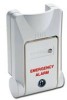
lever must be oriented vertically or horizontally as shown in the illustrations below. Desk Mount 0 46188 02709 5 3040/3050 SERIES PANIC SWITCH Installation Instructions IMPORTANT: You must allow at least 3" (7.62cm) of clearance above the mounting surface to accommodate the actuating lever once - GE 3050-W | Installation Instructions - Page 2
will actuate. Then the LED will latch and light or change to red (3050), indicating that the SPDT switch has been activated. Closing the handle rearms the Red Black Common Closed Loop (N.O.) Open Loop (N.C.) Positive Negative Electrical Loop Type Open or Closed Open or Closed Open or Closed
-
 1
1 -
 2
2
 |
 |

STEP 1 - MOUNTING
3. Drill pilot holes or start the screws. Connect the wire leads to
the terminal block (see wiring diagram).
4. After the leads are wired, install cover plate by snapping it in
place. Then, insert the screws through the switch housing and
firmly secure unit into place.
IMPORTANT: You must allow at least 3" (7.62cm) of clear-
ance above the mounting surface to accommodate the
actuating lever once it is fully open.
1. Determine the best location for the 3040/3050 based on the
work habits of the end user and their physical reach. The 3040
should be placed such that the user would not call attention
while activating the switch. Typical mounting positions are on
the sides of desks in the kneehole area, or under counters away
from view. The 3050 with its lit LED (green) is visible in low light
environments or at night. The unit should be mounted within the
line of sight, so that the LED is not obstructed. The device can
be located in a hall, entryway or near a bedside. The lever must
be oriented vertically or horizontally as shown in the illustrations
below.
Desk Mount
Maximum 3" Clearance
When Lever Fully Open
Lever
Actuates Between
20° and 45°
Wire
Leads
Screw
Holes
Cover
Plate
2. Temporarily position the unit where it will be mounted, and
mark the screw holes and the hole for the leads.
3040/3050 SERIES
PANIC SWITCH
Installation Instructions
Kneehole of Desk, Horizontal
Under Counter
Kneehole of Desk, Vertical
Freezer Mount
0
46188 02709
5
Phone: 800.894.0412 - Fax: 888.723.4773 - Web: www.clrwtr.com - Email: [email protected]