GE 60-504-10-319.5 Installation Instructions
GE 60-504-10-319.5 - Security Wireless Freeze Sensor Manual
 |
UPC - 046188089444
View all GE 60-504-10-319.5 manuals
Add to My Manuals
Save this manual to your list of manuals |
GE 60-504-10-319.5 manual content summary:
- GE 60-504-10-319.5 | Installation Instructions - Page 1
sensor in an area with excessive metal or electrical wiring. • install the sensor in areas with 10° to 120°F (-12° to 49°C). Programming The following steps provide a general guideline for programming (learning) the freeze sensor into panel memory. Refer to specific panel installation instructions - GE 60-504-10-319.5 | Installation Instructions - Page 2
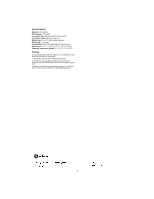
Specifications Model No: 60-742-95R RF Frequency: 319.5 MHz Transmitter Type: Surface Acoustical Wave (SAW) × 2.87 × 2.24 cm) Operating Temperature Range: 10° to 120°F (-12° to 49°C) Notices This device complies with FCC Rules Part 15. Operation is subject to the following two conditions:
-
 1
1 -
 2
2
 |
 |
1
,QVWDOODWLRQ±±,QVWUXFWLRQV
*(±6HFXULW\
'
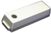
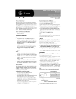
Product Summary
The freeze sensor detects low temperature conditions
which may indicate furnace failure. The sensor contains
a bimetallic thermal switch connected to a built-in trans-
mitter. When the surrounding temperature drops to
approximately 41°F (5°C), the sensor transmits an alarm
signal. When the surrounding temperature rises to 50°F
(10°C), the sensor transmits a restore signal.
Tools and Equipment Needed
•
Slotted screwdriver
Installation Guidelines
Do...
•
program and test the sensor
before
mounting it.
•
install the transmitter within 100 feet (30.5 m) of the
control panel. Although the transmitter has an open-
air range of 500 feet (152 m), the effective indoor
range may be less.
•
install the sensor in an area more likely to become
cold before other areas in the building; placing the
sensor in such an area ensures early warning.
•
install the sensor on an interior wall near a continuous
air flow.
Do not...
•
install the sensor in the same room as a furnace or
other heat source that stays warm after furnace failure.
•
install the sensor on an outside wall or basement floor.
•
install the sensor in an area with excessive metal or
electrical wiring.
•
install the sensor in areas with excessive moisture.
•
install the sensor where temperatures exceed the sen-
sor’s operating limits of 10° to 120°F (-12° to 49°C).
Programming
The following steps provide a general guideline for pro-
gramming (learning) the freeze sensor into panel mem-
ory. Refer to specific panel
installation instructions
for
complete programming details.
Programming for Simon
®
Panels:
1.
Set your control panel to
Program
mode.
2.
Proceed to
Learn Sensors
menu
.
3.
Remove the sensor’s outer cover by pressing the cover
release button located on the end of the sensor.
4.
Press and hold the plastic tab marked
Press to Pro-
gram
until the control panel confirms programming.
5.
Replace the sensor’s outer cover.
6.
Select sensor group and sensor number assignments.
7.
At the panel, exit
Program
mode.
Programming all other GE Panels:
1.
Set your control panel to
Program
mode.
2.
Proceed to
Learn Sensors
menu
.
3.
Select sensor group and sensor number assignments.
4.
Remove the sensor’s outer cover by pressing the cover
release button located on the end of the sensor.
5.
Press and hold the plastic tab marked
Press to Pro-
gram
until the control panel confirms programming.
6.
Replace the sensor’s outer cover.
7.
At the panel, exit
Program
mode.
Note
Refer to specific Quick Bridge
®
Loop Receiver documents
for additional programming information.
Testing
The following steps provide a general guideline for test-
ing the freeze sensor. Refer to specific panel
installation
instructions
for complete testing details.
1.
Set your control panel to
Sensor Test
mode.
2.
Trip the sensor by pressing and holding the plastic tab
marked
Press to Program
for at least one second.
3.
Listen for appropriate sirens as described in the panel
installation instructions. The sirens indicate the num-
ber of signals the panel has received from the sensor.
Installation
This section describes how to install the sensor after suc-
cessful programming and testing.
1.
Secure sensor base to a clean, dry, nonporous mount-
ing surface using the double-sided tape.
Or
follow steps 2-4 to secure sensor base with screws.
2.
Remove the sensor’s cover by pressing the cover
release button on the end of the sensor.
3.
Remove batteries and access the mounting holes.
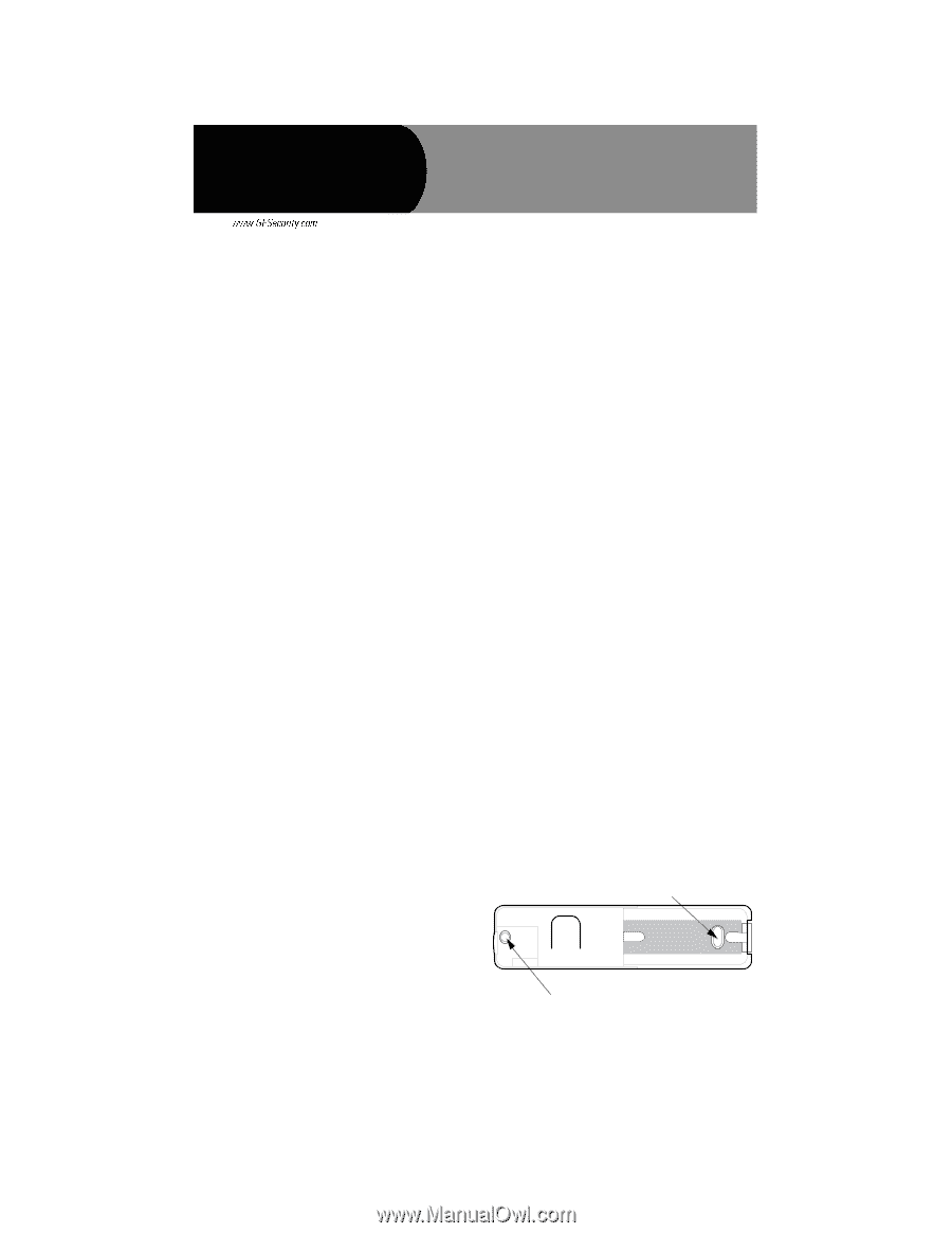
4.
Use the included screws to secure sensor base at each
mounting hole location (see Figure 1). Remember to
use an achor if mounting sensor on drywall or plaster.
Note
Mounting Hole #2 may not be accessible on all models.
5.
Install the AAA batteries and replace cover.
MOUNTING HOLE #1
9255G02A.D
SF
MOUNTING HOLE #2
Figure 1.
Mounting Hole Locations
6$:±/HDUQ±0RGH±)UHH]H
6HQVRU
Document No. 466-1541Rev. E
September 2004