GE 60-770 Installation Instructions
GE 60-770 - Security SuperBus 2000 4-Zone Output Module Manual
 |
UPC - 046188092215
View all GE 60-770 manuals
Add to My Manuals
Save this manual to your list of manuals |
GE 60-770 manual content summary:
- GE 60-770 | Installation Instructions - Page 1
Module ITI Part No. 60-770 Document Number: 466-1608 Rev. B November 2000 8557109A.DS4 Installation Instructions Product Summary Module Components Each SuperBus 2000 4-Relay Output module adds four programmable relay outputs to a compatible panel. Examples of module uses include: u Turning on - GE 60-770 | Installation Instructions - Page 2
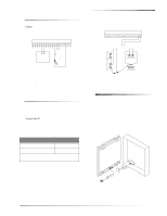
The relay output module can be mounted: u On a wall. u Inside an Advent cabinet. u Inside a Concord cabinet. u Inside a SuperBus Module cabinet (60-698). Refer to the cabinet Installation Instructions for installation procedures. CAUTION To prevent damaging the panel or card, disconnect the panel AC - GE 60-770 | Installation Instructions - Page 3
in Figure 5 (sup- plied with panel) into the panel circuit board. SUPPORT STANDOFF 1 2 3 4 5 6 7 8 9 10 11 12 13 14 15 16 17 18 MAGNET CLIP REED SWITCH HOLDER 9710G02B.DSF Figure 3. Mounting Holes Mounting the Module in an Advent Cabinet 1. Remove panel AC power and disconnect the backup - GE 60-770 | Installation Instructions - Page 4
by a nonconductive barrier. OR (B) Class 2, Class 3, and power-limited fire alarm circuit conductors must be installed as Class 1 or higher circuits. Wiring the Module to a Panel ID: XXXXXXXX 1 2 3 4 5 6 7 8 9 10 11 12 13 14 15 16 17 18 ZONE COM ZONE 1 GND** (BLK) BUS B (WHT) BUS A (GRN) +12 VDC - GE 60-770 | Installation Instructions - Page 5
cabinet, you must add module tamper detection for UL Listed systems. To do this, install a UL listed ¼-inch press-fit reed switch on the module back-plate and wire the switch to the module zone input terminals or unused panel hardwire input terminals. Once programmed, if someone opens the module - GE 60-770 | Installation Instructions - Page 6
red BUS status LED does not flash, remove AC panel power, disconnect the battery(s), and see Table 6 "Troubleshooting." Existing Installations Concord Panels- Same as new installation. Advent Panels- 1. Verify that all wiring between the panel and module is correct. 6 SuperBus® 2000 4-Relay Output - GE 60-770 | Installation Instructions - Page 7
on or the red BUS status LED does not flash, set the RUN/PROGRAM switch (UltraGard) to RUN, remove AC panel power, disconnect the backup battery, and see Table 6 "Troubleshooting." Programming and Testing Refer to the specific panel Installation Instructions for configuring module outputs, adding - GE 60-770 | Installation Instructions - Page 8
) Inputs: One supervised, fire-rated, hardwire zone Outputs: Four, panel programmable outputs with "Form-C" relay contacts (COMMON, N/C, N/O). Relay contacts rated 4A @ 24VDC, 4A @ 24VAC, 1A @ 70VAC maximum. Storage Temperature: -30° to 140° F (-34° to 60° C) Operating Temperature: 32° to 140
-
 1
1 -
 2
2 -
 3
3 -
 4
4 -
 5
5 -
 6
6 -
 7
7 -
8
 |
 |

1
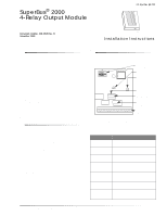
SuperBus® 2000 4-Relay Output Module
Installation Instructions
Product Summary
Each SuperBus 2000 4-Relay Output module adds four pro-
grammable relay outputs to a compatible panel.
Examples of module uses include:
Turning on a CCTV camera during a burglary alarm.
Turning on exit lights during a fire alarm.
Activating backup cellular phones or long-range radios
if primary communications are inoperable.
Each module comes complete with mounting hardware.
Power for the module is provided by the panel.
Advent
®
panels can be expanded to a total of 124 (24 pre-
programmed) output points.
UltraGard
®
and Concord
™
panels can be expanded to a total
of 32 output points.
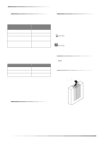
For additional security, the plastic case accommodates a
magnetic reed switch to provide tamper protection. Simply
connect a UL listed reed switch to the module built-in zone
input or to one of the fire/security panel hardwire input
zones.
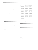
SuperBus 2000 vs. SuperBus
SuperBus 2000 panels have the ability to auto-address mod-
ule unit numbers. When the panel is initially powered up,
the panel automatically reads the unique SuperBus 2000
device ID number and assigns a unit number to the module.
This eliminates manually setting DIP switches and the
chance of identical unit number conflicts.
SuperBus 2000 Panels
Advent
Concord (software versions 2.0 and later)
SuperBus panels communicate with SuperBus 2000 mod-
ules but require the module unit number to first be set man-
ually with DIP switches.
SuperBus Panels
UltraGard
Concord (software versions 1.0–1.6)
Module Components
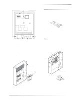
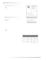
Figure 1 shows the main module components and Table 1
describes them.
Figure 1. Module Circuit Board Components
Table 1: Module Component Descriptions
Component
Function
Unit Number DIP
Switches
Used for manually setting module unit
number (SuperBus panels).
BUS LED (Red)
Flashes to indicate normal
communication with the panel.
POWER LED
(Green)
Indicates module power status.
Output Relays
Form C (dry contact) output relays rated
4A @ 24VDC, 4A @ 24VAC, 1A @
70VAC maximum.
SuperBus 2000
Device ID Number
Label
Identifies the unique device ID
(SuperBus 2000).
Software Version
Label
Identifies the installed software version.
Wiring Terminals
Used for power, bus, and output wiring
connections. All terminals are Class 2
power limited.
POWER LED
(GREEN)
SOFTWARE
VERSION LABEL
UNIT NUMBER
DIP SWITCHES
WIRING
TERMINALS
9710G01A.DSF
BUS STATUS LED
(RED)
OUTPUT RELAYS (4)
SUPERBUS 2000
DEVICE ID
NUMBER LABEL
SuperBus
®
2000
4-Relay Output Module
8557109A.DS4
ITI Part No. 60-770
Document Number: 466-1608 Rev. B
November 2000