GE 60-807-95R Installation Instructions
GE 60-807-95R - Pet Immune Wireless Motion Detector Manual
 |
UPC - 782136403831
View all GE 60-807-95R manuals
Add to My Manuals
Save this manual to your list of manuals |
GE 60-807-95R manual content summary:
- GE 60-807-95R | Installation Instructions - Page 1
ITI Part No. 60-807-95R, 60-807-43 Document Number: 466-1725 Rev. B April 2000 Product Summary A motion sensor (passive-infrared or PIR) detects movement within a specific area by sensing the infrared energy emitted from a body as it moves across the sensor's field of view. When this motion is - GE 60-807-95R | Installation Instructions - Page 2
the Sensitivity on the Indoor Motion Sensor DO NOT FLUSH MOUNT DO NOT MOUNT USING SWIVEL MOUNT For pet applications, the PIR must be set to standard sensitivity. Figure 4. Wall Mount Options: Use the inclined position for surface or corner mounting. 2 ITI® Pet Immune SAW PIR Motion Sensor - GE 60-807-95R | Installation Instructions - Page 3
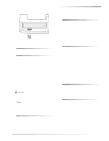
end is down and on the right side the positive end is up. When the battery is replaced, wait at least 3 minutes after installing the battery Turn on all heating or air conditioning sources which would normally be active during the protection period. Stand ITI® Pet Immune SAW PIR Motion Sensor 3 - GE 60-807-95R | Installation Instructions - Page 4
interference that may cause undesired operation. Changes or modifications not expressly approved by Interactive Technologies, Inc. can void the users' authority to operate the equipment. ITI is a registered trademark of Interactive Technologies, Inc. 4 ITI® Pet Immune SAW PIR Motion Sensor
-
 1
1 -
 2
2 -
 3
3 -
 4
4
 |
 |

1
ITI® Pet Immune SAW PIR Motion Sensor
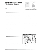
Product Summary
A motion sensor (passive-infrared or PIR) detects move-
ment within a specific area by sensing the infrared energy
emitted from a body as it moves across the sensor’s field of
view.
When this motion is detected, the sensor transmits an
alarm signal to the control panel.
Use this motion sensor to protect locations where door/win-
dow sensors are impractical or not needed. For example,
use a motion sensor to protect large areas or open floor
plans. Motion sensors also provide backup protection for
door/window sensors.
The ITI
®
Pet Immune SAW PIR utilizes advanced signal
processing, a new custom designed lens, and a new custom
designed sensing element.
The combination of these
improvements provides false alarm immunity for pets with
a combined weight of up to 40 pounds while still providing
superior human catch performance.
This wireless motion sensor includes the following features:
35 feet by 40 feet coverage area
Three minute transmitter lockout time after an alarm
that helps extend battery life
Cover-activated tamper (optional wall-activated tamper
is included)
Supervisory signals transmitted every 64 minutes to the
control panel
Sensor low battery reports (trouble) to the control panel
Field-selectable sensitivity options (standard setting
required for pet applications)
Installation Guidelines
This PIR was designed for indoor use in the presence of
pets having a combined weight of up to 40 pounds.
The fol-
lowing installation guidelines must be met to provide this
false alarm immunity.
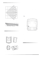
The sensor must be incline-mounted on a wall surface
or incline mounted in a corner at a mounting height of
7.5 feet. See Figure 4.
The sensitivity switch must be set to Standard.
The pet must not be allowed to climb on objects such as
furniture, boxes, etc. within the field of coverage.
See
Figures 2 and 3 to determine the sensor’s field of cov-
erage.
Room temperature must be kept between 60º and
120° F.
If possible, locate sensors within 100 feet of the panel.
While a transmitter may have a range of 500 feet or
more out in the open, the environment at the installa-
tion site can have a significant effect on transmitter
range.
Sometimes a change in sensor location can help
overcome adverse wireless conditions.
Position the sensor to protect an area where an intruder
would be most likely to walk
across
the detection pat-
tern (see Figure 1).
Mount the motion sensor on an insulated, outside wall
facing in.
Mount the motion sensor on a rigid surface which is
free from vibrations.
Position the sensor so it faces a solid reference point,
like a wall.
Do not aim the sensor at windows, fireplaces, air condi-
tioners, area heaters, forced air heating vents, or place
it in direct sunlight.
Do not mount the sensor near duct work or other large
metallic surfaces which may affect the RF signals (see
“Final Testing” on page 4).
Actual acceptable transmit-
ter range should be verified for each installation.
Mount the sensor permanently on a flat wall or in a cor-
ner.
Do not set it on a shelf.
Windows should be closed in any area which has an
armed motion sensor.
Figure 1. Overhead (Bird’s Eye View) Detection Path
8362G04B.DS4
Person walking across detection path
±²±
±
³´µ¶³±··¸¹µ³º»¼³
´±½³¾¿¶À¿¹³ºµ¹Á¿Â
8362G12A.DS4
1061G37A.DS4
ITI Part No. 60-807-95R, 60-807-43
Installation Instructions
Document Number: 466-1725 Rev. B
April 2000