GE DCVH680EJMS Installation Instructions
GE DCVH680EJMS - 7.0 cu.ft. Electric Dryer Manual
 |
UPC - 084691177180
View all GE DCVH680EJMS manuals
Add to My Manuals
Save this manual to your list of manuals |
GE DCVH680EJMS manual content summary:
- GE DCVH680EJMS | Installation Instructions - Page 1
accordance with the instructions found in "Connecting The Dryer To House Vent" on page 5 of this manual. Flexible venting materials instructions. (Installers: Be sure to leave these instructions with the customer). NOTE: Installation and service of this dryer requires basic mechanical and electrical - GE DCVH680EJMS | Installation Instructions - Page 2
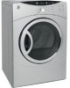
to provide adequate clearance for installation and service. 1 PREPARING FOR INSTALLATION OF NEW DRYER 2 ELECTRICAL CONNECTION INFORMATION TIP: Install your dryer before installing your washer. This will allow better access when installing dryer exhaust REMOVING LINT FROM WALL EXHAUST OPENING - GE DCVH680EJMS | Installation Instructions - Page 3
Installation Instructions 1. Turn off the circuit breaker(s) (30 amp) or remove the dryer's circuit fuse at the electrical box. 2. Be sure the dryer cord is the dryer life. • Accumulate lint, creating a potential fire hazard. The correct exhaust installation is YOUR RESPONSIBILITY. Problems due to - GE DCVH680EJMS | Installation Instructions - Page 4
flexible metal (semi-rigid or foil-type) duct to connect the dryer to the home exhaust duct. It must be installed in accordance with the instructions found in "Connecting The Dryer To House Vent" on page 5 of this manual. • Do not terminate exhaust in a chimney, a wall, a ceiling, gas vent, crawl - GE DCVH680EJMS | Installation Instructions - Page 5
Instructions, Exhausting CONNECTING THE DRYER closet contains both a washer and a dryer, doors must contain a dryer MUST be vented to the outdoors. See EXHAUST INFORMATION section 3 & 4. • The installation must conform with local codes or, in the absence of local codes, with the NATIONAL ELECTRICAL - GE DCVH680EJMS | Installation Instructions - Page 6
Installation Instructions 9 DRYER EXHAUST TO RIGHT, LEFT OR BOTTOM CABINET WARNING - BEFORE PERFORMING THIS EXHAUST INSTALLATION, BE SURE TO DISCONNECT THE DRYER FROM ITS ELECTRICAL SUPPLY. PROTECT YOUR HANDS AND ARMS FROM SHARP EDGES WHEN WORKING INSIDE THE CABINET. BE SURE TO WEAR GLOVES. ADDING - GE DCVH680EJMS | Installation Instructions - Page 7
switch them back to the right side, follow these same instructions and reverse all references to the left and right . WE1M454) available from your local service provider. Place dryer in final location. WARNING - NEVER Nut (#8) - 2 Washer - 2 Tapping Screw (#8) ... 2 Machine Screw (#8) ... 6 - GE DCVH680EJMS | Installation Instructions - Page 8
Installation Instructions BEFORE YOU START 1. Unplug the dryer from its electrical outlet. 4. Lay the door down on a soft Remove the 4 screws starting from the bottom to the top. Make sure the door is supported while removing the screws. Remove the four screws. 2 #8 Machine Screws 6. With the - GE DCVH680EJMS | Installation Instructions - Page 9
Installation Instructions REMOVE HINGE IMPORTANT: Note the location of the hinge (left . 12. Loosely fasten the hinge assembly to the edge using 2 machine screws (#8). 9. Remove the 2 nuts, washers, and the 2 machine screws (#8). 13. Hold the door on its side with one hand and fasten the remaining - GE DCVH680EJMS | Installation Instructions - Page 10
Installation Instructions REINSTALL NUTS AND HINGE COVER 14. Place the door on its edge. Assemble the 2 machine screws (#8), washers, and nuts. Tighten using a wrench and screwdriver. REASSEMBLE DOOR ASSEMBLY IMPORTANT: Make sure there is no dirt or any other foreign material in between the - GE DCVH680EJMS | Installation Instructions - Page 11
on the opposite side. 11 SERVICING WARNING - LABEL ALL WIRES PRIOR TO DISCONNECTING WHEN SERVICING CONTROLS. WIRING ERRORS CAN CAUSE IMPROPER AND DANGEROUS OPERATION AFTER SERVICING/INSTALLATION. For replacement parts and other information, refer to Owner's Manual for servicing phone numbers. 11 - GE DCVH680EJMS | Installation Instructions - Page 12
ROUGH-IN DIMENSIONS 27" 27" 31 1/8" 1 5/8" 41 1/2" 4 1/2" 30 5/8" 11 3/4" 53 5/8" 40 1/4" 39 1/8" 17" 13 3/8" 11 3/4" 12
-
 1
1 -
 2
2 -
 3
3 -
 4
4 -
 5
5 -
 6
6 -
 7
7 -
8
-
9
-
10
-
11
-
12
 |
 |

Questions or Installation? Call: 1-800-GECARES (US)
or
Visit our Web site at:
www.GEAppliances.com (US)
Installation
Instructions
Electric Dryer
09
Step 1
Prepare the Area and Exhaust for Installation of New
Dryer (see section 1).
Step 2
Check and Ensure the Existing External Exhaust is
Clean (see section 1) and Meets Attached Installation
Specifications (see section 3).
Step 3
Remove the Foam Shipping Pads (see section 1).
Step 4
Move the Dryer to the Desired Location.
Step 5
Connect the Power Supply (see section 2).
Step 6
Connect the External Exhaust (see section 4).
Step 7
Level Your Dryer (see section 5).
Step 8
Check the Operation of the Power Supply and
Venting.
Step 9
Place the Owners Manual and the Installation
Instructions in a Location Where They Will Be
Noticed By the Owner.
For Alcove or Closet Installation, see section 6.
For Bathroom or Bedroom Installation, see section 7.
For Mobile or Manufactured Home see, section 8.
For side or bottom exhaust, see section 9.
500A436P009_Rev0
Pub # 31-16228
PEDESTALS FOR DRYERS
(comes with individual installation instructions)
Three models available:
- SBSD227F
- SBSD137H
- SBSD107H
NOTE:
Installation and service of this dryer
requires basic mechanical and electrical skills.
It is your responsibility to contact a qualified
installer to make the electrical connections.
BEFORE YOU BEGIN
Read these instructions completely and carefully.
•
IMPORTANT-
Save these instructions for local
inspector’s use.
•
IMPORTANT-
Observe all governing codes and
ordinances.
•
Note to Installer
- Be sure to leave these instructions with
the customer.
•
Note to Customer
- Keep these instructions with your Use
and Care Book for future reference.
•
Before the old dryer is removed from service or discarded,
remove the dryer door.
•
Service information and the wiring diagram are located in
the control console.
•
Do not allow children on or in the appliance.
Close super-
vision of children is necessary when the appliance is used
near children.
•
Install the dryer where the temperature is above 50°F for
satisfactory operation of the dryer control system.
MATERIALS YOU WILL NEED
GLOVES
SAFETY
GLASSES
DRYER POWER CORD
KIT (NOT PROVIDED
WITH DRYER)
4" DUCT
CLAMPS (2)
OR
4" SPRING
CLAMPS (2)
EXHAUST
HOOD
3/4" STRAIN
RELIEF
UL RECOGNIZED
4" DIA. METAL
ELBOW
4" DIA. FLEXIBLE METAL (SEMI-RIGID)
UL LISTED TRANSITION DUCT
(IF NEEDED)
KIT WX08X10077 (INCLUDES 2 ELBOWS)
4" DIA. METAL DUCT
(RECOMMENDED)
4" DIA. FLEXIBLE METAL (FOIL TYPE)
UL LISTED TRANSITION DUCT
(IF NEEDED.)
DUCT TAPE
UL RATED
120/240V,30A
WITH 3 OR 4 PRONGS.
IDENTIFY THE PLUG
TYPE AS PER THE
HOUSE RECEPTACLE
BEFORE PURCHASING
LINE CORD.
TOOLS YOU
WILL NEED
SLIP JOINT PLIERS
FLAT BLADE SCREWDRIVER
PHILLIPS SCREWDRIVER
LEVEL
- RISK OF FIRE
WARNING
•
To reduce the risk of severe injury or death, follow all installation instructions.
•
Clothes dryer installation must be performed by a qualified installer.
•
Install the clothes dryer according to these instructions and in accordance
with local codes.
•
This dryer must be exhausted to the outdoors.
•
Use only 4” rigid metal ducting for exhausting the clothes dryer to the
outdoors.
•
Do not install or store this appliance in any location where it could be
exposed to water and or weather.
•
Save these instructions.
(Installers: Be sure to leave these instructions with
the customer).
•
DO NOT install a clothes dryer with flexible plastic ducting materials.
If flexible metal (semi-rigid or foil-type) duct is installed, it must be UL listed
and installed in accordance with the instructions found in "Connecting The
Dryer To House Vent" on page 5 of this manual.
Flexible venting materials
are known to collapse, be easily crushed, and trap lint.
These conditions will
obstruct dryer airflow and increase the risk of fire.