GE GTUP270EMWW Installation Instructions
GE GTUP270EMWW Manual
 |
UPC - 084691229018
View all GE GTUP270EMWW manuals
Add to My Manuals
Save this manual to your list of manuals |
GE GTUP270EMWW manual content summary:
- GE GTUP270EMWW | Installation Instructions - Page 1
governing codes and ordinances. • Note to Installer - Be sure to leave these instructions with the customer. • Note to Customer - Keep these instructions with your Use and Care Book for future reference. • Before the appliance is removed from service or discarded, remove the washer and dryer door - GE GTUP270EMWW | Installation Instructions - Page 2
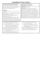
. ELECTRICAL REQUIREMENTS CAUTION: Before plugging in washer, read the follow- ing electrical requirements Clean (see section 1) and Meets Attached Installation Specifications (see section 6). Step 4 Remove the the Owners Manual and the Installation Instructions in a Location Where They Will Be - GE GTUP270EMWW | Installation Instructions - Page 3
Installation Instructions 24" NOMINAL PRODUCT DIMENSIONS *23.75" 43" 17.9" 74.5" Vent 8.2" 51° 51" 26" Water inlets (rear) 4.1" Drain outlet (rear) 4.2" 37" 32.7" 19.1" 23.75" 27. - GE GTUP270EMWW | Installation Instructions - Page 4
. NEW HOME OR REMODELING FAUCETS/ DRAIN STANDPIPE/ELECTRICAL LOCATION Right side of Unitized Washer/ Dryer. 12" Locate spigots, drain standpipe and electrical plug in this area 42" 33" FLOOR 2 GAS REQUIREMENTS WARNING • Installation must conform to local codes and ordinances, or in their absence - GE GTUP270EMWW | Installation Instructions - Page 5
Installation Instructions GAS SUPPLY • A 1/8-in.National Pipe Taper thread plugged tapping, accessible for test gauge connection, must be installed immediately upstream of the gas supply connection to the dryer. Contact your local gas utility should you have questions on the installation of the - GE GTUP270EMWW | Installation Instructions - Page 6
by a 15- or 20- amp circuit breaker or timedelay fuse. If electrical supply provided does not meet the above specifications, it is recommended that a licensed electrician install an approved outlet. WARNING - THIS DRYER IS EQUIPPED A THREE-PRONG (GROUNDING) PLUG FOR YOUR PROTECTION AGAINST SHOCK - GE GTUP270EMWW | Installation Instructions - Page 7
flexible metal (semi-rigid or foil-type) duct to connect the dryer to the home exhaust duct. It must be installed in accordance with the instructions found in "Connecting The Dryer To House Vent" on page 8 of this manual. •Do not terminate exhaust in a chimney, a wall, a ceiling, gas vent, crawl - GE GTUP270EMWW | Installation Instructions - Page 8
Installation Instructions top of back part of the washer lid and used (Kit WX08X10077). • Never install flexible metal Canada and the United States, only the flexible metal(foiltype) ducts that comply with the "Outline for Clothes Dryer Transition Duct Subject 2158A" shall be used. • Never install - GE GTUP270EMWW | Installation Instructions - Page 9
Installation Instructions DO C C H H ELBOW HIGHLY RECOMMENDED C H EXHAUST TO LEFT OR RIGHT SIDE OF AGAINST WALL 9 DRYER EXHAUST TO RIGHT, LEFT OR BOTTOM CABINET WARNING - BEFORE PERFORMING THIS EXHAUST INSTALLATION, BE SURE TO DISCONNECT THE APPLIANCE FROM ITS ELECTRICAL SUPPLY. PROTECT YOUR - GE GTUP270EMWW | Installation Instructions - Page 10
rear of washer. Hand tighten, plus an additional 1/8 turn with pliers. Move appliance as close to final location as possible, leaving room for you to make water, drain, electrical and vent connections to your home. NOTE: If longer drain hose is required, order drain hose extension kit, GE part number - GE GTUP270EMWW | Installation Instructions - Page 11
equal 72 square inches. 14 BATHROOM OR BEDROOM INSTALLATION • The appliance MUST be vented to the outdoors. See EXHAUST INFORMATION section 6 & 7. • The installation must conform with local codes or, in the absence of local codes, with the NATIONAL ELECTRICAL CODE, ANSI/NFPA NO. 70 and NATIONAL FUEL - GE GTUP270EMWW | Installation Instructions - Page 12
Installation Instructions 15 SERVICING WARNING- LABEL ALL WIRES PRIOR TO DISCONNECTION WHEN SERVICING CONTROLS. WIRING ERRORS CAN CAUSE IMPROPER AND DANGEROUS OPERATION AFTER SERVICING/INSTALLATION. For replacement parts and other information, refer to Owner's Manual for servicing phone numbers. TO - GE GTUP270EMWW | Installation Instructions - Page 13
DESCONEXIÓN CUANDO SE REALICEN CONTROLES DEL SERVICIO TÉCNICO. CUALQUIER ERROR DE CABLEADO PUEDE OCASIONAR UN FUNCIONAMIENTO INADECUADO Y PELIGROSO LUEGO , consulte los números telefónicos del servicio técnico en el Manual del Propietario. PARA REGISTRAR SU SECADORA LLAME AL NÚMERO GRATUITO 1- - GE GTUP270EMWW | Installation Instructions - Page 14
DEBE SER DE METAL. • Se DEBERÁ usar el KIT 14-D346-33 para adherir la secadora a la estructura de parte superior e inferior. Se requiere que las aberturas de aire no estén obstruidas cuando se instale NACIONAL DE ELECTRICIDAD (NATIONAL ELECTRICAL CODE), ANSI/NFPA NO. 70 y el CÓDIGO - GE GTUP270EMWW | Installation Instructions - Page 15
además, se DEBERÁ instalar una desviación del sifón en la parte trasera de la máquina. Use el Kit de Desviación del Sifón WH49X228 y siga las instrucciones del mismo. 11 CONEXIÓN A INSTALACIONES DE PLOMERÍA c H Si no se encuentra instalada, instale la arandela de goma en un extremo de la manguera - GE GTUP270EMWW | Installation Instructions - Page 16
Instrucciones de Instalación QUÉ HACER C C H H CODO ALTAMENTE RECOMENDADO C H ESCAPE HACIA LA IZQUIERDA O DERECHA DEL GABINETE • Para que el conducto salga hacia uno de los laterales, quite el separador (SÓLO 1). Gire las secciones del codo de modo que apunten hacia el costado. Realice un - GE GTUP270EMWW | Installation Instructions - Page 17
su ubicación final, coloque un nivel sobre la parte trasera de la tapa de la lavadora y controle semi-rígido) de la lista de UL (Kit WX08X10077). • Nunca instale un conducto de metal flexible en paredes, " (Outline for Clothes Dryer Transition Duct Subject 2158A). • Nunca instale un conducto de metal - GE GTUP270EMWW | Installation Instructions - Page 18
forma superpuesta con cinta para conducto. • Las partes horizontales deberán tener una caída de ½" Ventilación del Hogar" en la página 8 de este manual. •No termine la salida del escape en una chimenea, pared creando un posible riesgo de incendio. •Nunca instale una rejilla en o sobre el conducto de - GE GTUP270EMWW | Installation Instructions - Page 19
locales, de acuerdo con el CÓDIGO NACIONAL DE ELECTRICIDAD (NATIONAL ELECTRICAL CODE), ANSI/NFPA NO. 70. REQUISITOS ELÉCTRICOS Este electrodoméstico las especificaciones anteriores, se recomienda que un electricista matriculado instale un tomacorriente aprobado. ADVERTENCIA - ESTA SECADORA ESTÁ - GE GTUP270EMWW | Installation Instructions - Page 20
sellado para rosca de tubería o cinta de teflón apropiada para gas natural o LP. • Se deberá usar con la secadora un conector metálico flexible que DE LA LÍNEA DE GAS DE METAL FLEXIBLE 24" ENTRADA DEL ELECTRODOMÉSTICO PARTE TRASERA DEL ELECTRODOMÉSTICO 24" & 27" LLAMA ENTRADA DE NPT DE 3/8" - GE GTUP270EMWW | Installation Instructions - Page 21
a ambos lados y 1 pulgada en la parte trasera. Se deberá considerar que se debe DIGO NACIONAL DE GAS COMBUSTIBLE (NATIONAL FUEL GAS CODE), ANSI Z223. •Esta secadora a gas está kit de conversión WE25X0217, su organización del servicio local puede convertir la secadora para su uso con gas propano (LP - GE GTUP270EMWW | Installation Instructions - Page 22
Instrucciones de Instalación DIMENSIONES NOMINALES DEL PRODUCTO DE 24" *23.75" 43" 17.9" 74.5" Ventilación 8.2" 51° 51" 26" Entradas de agua (trasera) 4.1" Salida de drenaje (trasera) 4.2" 37" 32.7" 19.1" 23.75" 27.25" * La dimensión representa la puerta cerrada incluyendo la manija y las - GE GTUP270EMWW | Installation Instructions - Page 23
y la frecuencia indicados en la placa de especificaciones (ubicada en la parte superior del panel frontal de la lavadora), y estar conectado a un Corriente, las Conexiones de Gas, y la Ventilación. Paso 12 Coloque el Manual del Propietario y las Instrucciones de Instalación en una Ubicación Donde el - GE GTUP270EMWW | Installation Instructions - Page 24
cerca.• Instale la calificado. • Instale el electrodom and Propane Installation Code), CSA LP salida al exterior. • NO instale una secadora de ropa con gina 8 de este manual. Se sabe que No instale ni UL (SI ES NECESARIO)KIT WX08X10077 (INCLUYE 2 CODOS) SI ES NECESARIO) (KIT WE1M454) Llave para Turcas
-
 1
1 -
 2
2 -
 3
3 -
 4
4 -
 5
5 -
 6
6 -
 7
7 -
8
-
9
-
10
-
11
-
12
-
13
-
14
-
15
-
16
-
17
-
18
-
19
-
20
-
21
-
22
-
23
-
24
 |
 |

WARNING
RISK OF FIRE
• To reduce the risk of severe injury or death, follow all installation instructions.
• Appliance installation must be performed by a qualified installer.
• Install the clothes appliance according to these instructions and in accordance with local
codes. In the absence of local codes, installation must comply with National Fuel Gas
Code, ANSIZ223.1/NFPA 54 or the Canadian Natural Gas and Propane Installation Code,
CSA B149.1.
•
California Safe Drinking Water and Toxic Enforcement Act.
This act requires the governor of California to publish a list of substances known to the
state to cause cancer, birth defects or other reproductive harm and requires businesses
to warn customers of potential exposure to such substances. Gas appliances can
cause minor exposure to four of these substances, namely benzene, carbon monoxide,
formaldehyde and soot, caused primarily by the incomplete combustion of natural gas or
LP fuels. Properly adjusted dryers will minimize incomplete combustion. Exposure to these
substances can be minimized further by properly venting the dryer to the outdoors.
• This appliance must be exhausted to the outdoors.
• Use only 4” rigid metal ducting for exhausting the appliance to the outdoors.
•
DO NOT
install a clothes dryer with flexible plastic ducting materials. If flexible metal
(semi-rigid or foil-type) duct is installed, it must be UL listed and installed in accordance
with the instructions found in “Connecting The Dryer To House Vent” on page 8 of this
manual. Flexible venting materials are known to collapse, be easily crushed, and trap lint.
These conditions will obstruct dryer airflow and increase the risk of fire.
• Do not install or store this appliance in any location where it could be exposed to water
and or weather.
• Save these instructions. (Installers: Be sure to leave these instructions with the customer).
In the state of Massachusetts, installation must be performed by a qualifiedor
licensed contractor, plumber, or gasfitter qualified or licensed by the state.
Installation
Instructions
Unitized Gas
Washer/Dryer
Questions on Installation? Call: 1-800-GECARES (US)
or Visit our Web site at:
www.GEAppliances.com (US)
BEFORE YOU BEGIN
Read these instructions completely and
carefully.
•
IMPORTANT-
Save these instructions for
local inspector’s use.
•
IMPORTANT-
Observe all
governing codes
and ordinances.
•
Note to Installer -
Be sure to leave these
instructions with the customer.
•
Note to Customer -
Keep these instructions
with your Use and Care Book for future
reference.
• Before the appliance is removed from service
or discarded, remove the washer and dryer
door.
• Inspect the dryer exhaust outlet and straighten
the outlet walls if they are bent.
• Service information and the wiring diagram
are located at the access panel.
• Do not allow children on or in the appliance.
Close supervision of children is necessary when
the appliance is used near children.
• Install the dryer where the temperature is
above 50°F for satisfactory operation of the
dryer control system.
LEVEL
8" PIPE WRENCH
10" ADJUS
TABLE WRENCHES
(x2)
TOOLS YOU
WILL NEED
SLIP JOINT PLIERS
FLAT BLADE SCREWDRIVER
MATERIALS YOU WILL NEED
EXHAUST HOOD
FLEXIBLE GAS LINE CONNECTOR
SOAP SOLUTION
FOR LEAK DETECTION
PIPE
COMPOUND
DUCT TAPE
GLOVES
SAFETY GLASSES
4" DIAM METAL ELBOW
4" DUCT CLAMPS
OR
4" SPRING CLAMPS
(x2)
(x2)
4" DIA. FLEXIBLE METAL (SEMI-RIGID)
UL LISTED TRANSITION DUCT
(IF NEEDED)
KIT WX08X10077 (INCLUDES 2 ELBOWS)
4" DIA. METAL DUCT
(RECOMMENDED)
4" DIA. FLEXIBLE METAL (FOIL TYPE)
UL LISTED TRANSITION DUCT
(IF NEEDED.)
4" COVER PLATE (IF NEEDED)
(KIT WE1M454)
189D7219P001
31-16655
10/29/10 GE
D
E
S
I
G
N
C
E
R
T
I
F
I
E
D
PARTS SUPPLIED
2 Rubber Washers
2 Stainer Screens/
Ruuber Washers
(washers may be in water hoses)
2 Washer Hoses
1 Cable Tie
1/4” Nutdriver