GE JD750SFSS Installation Instructions
GE JD750SFSS Manual
 |
View all GE JD750SFSS manuals
Add to My Manuals
Save this manual to your list of manuals |
GE JD750SFSS manual content summary:
- GE JD750SFSS | Installation Instructions - Page 1
Installation Instructions 30" Electric Drop-In Ranges Questions?Call800.GE.CARES(800.432.2737)orVisitourWebsiteat:www.GEAppliances.com. InCanada,call1.800.561.3344orvisitwww.GEAppliances.ca. BEFORE YOU BEGIN Read these instructions carefully and completely. •IMPORTANT - Save - GE JD750SFSS | Installation Instructions - Page 2
InstallationInstructions 1 REMOVE PACKAGING MATERIALS Failuretoremovepackagingmaterialscouldresultindamagetotheappliance.Removeallpackingparts ONLY) NOTE: Drop-In Ranges are designed to hang from the countertop only. Do not install on a platform or support rails. Allow30"minimum - GE JD750SFSS | Installation Instructions - Page 3
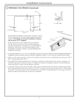
InstallationInstructions 2 PREPARING THE OPENING (Continued) 9/16"min. flat Wall 1/4"min.flat 23-3/16" 25" typically 9/16"min. flat Flat area R 1/4" 29-15/16"-30-1/16" smoothcut Rangesupport TheStandardInstallationofthisDrop-InRangeistohang bythecountertoponthe - GE JD750SFSS | Installation Instructions - Page 4
InstallationInstructions 3 WHEN INSTALLING RANGE IN COUNTERTOP CUT OUT TO THE WALL Ifthecounteropeningextendstothewalls,itwillrequiremaintopfillerkit(JXS66XX)orback-guardkit(JXS36XX, JXS39SS,orJXS32XX)toclosethegap.Refertothefillerorbackguardkitinstructionsfor - GE JD750SFSS | Installation Instructions - Page 5
InstallationInstructions 5A ELECTRICAL REQUIREMENTS WARNINGElectric Shock Hazard •Thisappliancemustbeproperlygrounded. •Donotuseanextensioncord. •Beforeinstallingrange,switchpoweroffattheservicepanelandlocktheservicedisconnectingmeans topreventpowerfrombeing - GE JD750SFSS | Installation Instructions - Page 6
InstallationInstructions 5B MAKE ELECTRICAL CONNECTIONS Placetheunitonaplatformortableevenwiththecutoutopening.Theplatformmustsupport200lbs.(91kg). Connecttheflexibleconduittotheelectricaljunctionboxasfollows: THREE-CONDUCTOR BRANCH CIRCUIT CONNECTION NOTE:If - GE JD750SFSS | Installation Instructions - Page 7
InstallationInstructions 6 ANTI-TIP DEVICE INSTALLATION WARNING •Toreducetheriskoftippingtherange,therangemustbeproperlysecuredtothecountertoporrearwall usingtheanti-tipsuppport .(Seesection3fordetails.) •Weightonthedoorcouldpotentiallycausetherangetotip - GE JD750SFSS | Installation Instructions - Page 8
InstallationInstructions 7 INSTALL THE RANGE INSTALL STOP SCREW Thesescrewspreventtherangefromslidingoutof positionduringoperation. 1.Carefullymarkthecabinetforthelocationofthe stopscrews. 2.Drill1/8"pilotholesintocabinet,oneachsideof therange.(Donotdrill - GE JD750SFSS | Installation Instructions - Page 9
InstallationInstructions 7 INSTALL THE RANGE (Continued) ATTACH THE LOWER TRIM Attachthelowertrim(suppliedseparatelywiththe range)tothebottomoftheverticalsidetrimwiththe 4screwssupplied. Side trim Lower Trim Attach2 screws each side Lower right endof front - GE JD750SFSS | Installation Instructions - Page 10
InstallationInstructions isinservicetothe appliancehasbeenturnedonandsurfaceelementshave heated 10 OPERATION CHECKLIST • ChecktomakesuretheClockdisplayisenergized.Ifaseriesofhorizontalredlinesappearinthedisplay, disconnectpowerimmediately.Rechecktherange - GE JD750SFSS | Installation Instructions - Page 11
Notes 11 - GE JD750SFSS | Installation Instructions - Page 12
12 PrintedintheUnitedStates - GE JD750SFSS | Installation Instructions - Page 13
" ¿Preguntas?Llameal1.800.GE.CARES(1.800.432.2737)ovisite visible,comounaetiqueta. ADVERTENCIALainformacióndeestemanualdebeseguirsealpiedelaletraafindeminimizar niño o adulto pueden volcar la cocina y morir. Instale el dispositivo anti-volcaduras (tornillos o soporte) de - GE JD750SFSS | Installation Instructions - Page 14
informativoylasbandejasdelhorno.Quite elrebordeinferiordelapartelateraldelhorno.Secolocaráalfinaldelprocesodeinstalación.El empotrables son diseñadas para colgar de la base únicamente. No instale sobre una plataforma de rieles con soportes. 20-5/8" Espacio hasta la puerta - GE JD750SFSS | Installation Instructions - Page 15
ser instalada sobre una base o subestructura (soporte de 2" x 4"). Base Silaconstruccióndesugabinetenopuedebrindarunárea planade¼"enlapartetraseradelaaberturadelabase, considerelaposibilidaddecambiarlabaseparaquese acomodeaestadimensión.Sieláreanoes - GE JD750SFSS | Installation Instructions - Page 16
Instruccionesdeinstalación 3 CUANDO INSTALE LA COCINA EN UN MOSTRADOR QUE TIENE UN RECORTE EN LA PARED Silaaberturadelabaseseextiendehastalasparedes,requeriráunkitderellenodelabasedelaparte superior(JXS66XX)ounkitdeproteccióntrasera(JXS36XX,JXS39SSoJXS32XX)para - GE JD750SFSS | Installation Instructions - Page 17
elCódigoEléctricoNacionalrequierequelasnuevasconstrucciones (noexistentes)utilicenunaconexióndecuatroconductoresaunhornoeléctrico.Cuandoinstaleunhorno eléctricoenunaconstrucciónnueva,unacasarodante,unvehículorecreativoounáreadondeloscódigos localesprohíben - GE JD750SFSS | Installation Instructions - Page 18
delcircuitoderivadodeacuerdocon loscódigoslocales,utilizandotaponesdealambre. Negro Circuito ramificado 3.Instaleunaabrazaderaadecuadadealiviode tensión. 4.Instalelatapadelacajadeconexiones. Rojo Cablesatierra yneutrales (blanco) Agujerociego alternativo - GE JD750SFSS | Installation Instructions - Page 19
. Instalación de los Soportes Anti-Volcaduras Seleccionelaposicióncorrectadeacuerdoalgrosorde Elsoporteanti-volcadurasseencuentraadherido alapartetraseradelaCocinaEmpotrable.Fue labaseymuevaelsoportehastalaposiciónadecuada. (Launidadseentregaconelsoporteen - GE JD750SFSS | Installation Instructions - Page 20
laspestañasmetálicaslateralesdebajodelvidrio sobrelosextremosdelaaberturadelabase. 2.Concuidado,deslicelacocinahacialaparte traseradelaabertura.Dejedeempujarlacocina cuandoaúnhayaunespaciode4"enelfrente, antesdecolocarlacocinaalrasde - GE JD750SFSS | Installation Instructions - Page 21
cocinadebajodela puerta.Lostornillossuperioresdeberánestar ubicadosenelagujerosobreloscostadosdela cocina,ynotocarlapartesuperiordelagujero cuandolacocinaseencuentretotalmenteubicada sobrelabase.Silostornillosnocumplenconlos requisitos,muevalosmismos - GE JD750SFSS | Installation Instructions - Page 22
,hasta laposicióndebloqueo.Cierrelapuerta. Bisagraenlaposición bloqueada Aberturadela bisagraajustada enformasegura enlaparte inferiordela ranuradela bisagra 9 LISTADO DE CONTROL FINAL • Verifiquequeelinterruptordecircuitosseencuentrecerrado(RESET)oque - GE JD750SFSS | Installation Instructions - Page 23
Notas 11 - GE JD750SFSS | Installation Instructions - Page 24
12 ImpresoenlosEstadosUnidos
-
 1
1 -
 2
2 -
 3
3 -
 4
4 -
 5
5 -
 6
6 -
 7
7 -
8
-
9
-
10
-
11
-
12
-
13
-
14
-
15
-
16
-
17
-
18
-
19
-
20
-
21
-
22
-
23
-
24
 |
 |

1
31-10829
GE 10-11
BEFORE YOU BEGIN
Read these instructions carefully and completely.
•
IMPORTANT
—
Save these instructions for
local inspector’s use.
•
IMPORTANT
—
Observe all governing
codes and ordinances.
•
Note to Installer –
Be sure to leave these
instructions with the consumer.
•
Note to Consumer –
Keep these instructions for
future reference.
•
Skill level –
Installation of this appliance requires a
qualified installer or electrician.
• Proper installation is the responsibility of the installer.
• Product failure due to improper installation is NOT
covered under the warranty.
30” Electric
Drop-In Ranges
Installation
Instructions
Questions?
Call 800.GE.CARES (800.432.2737) or Visit our Website at: www.GEAppliances.com.
In Canada, call 1.800.561.3344 or visit www.GEAppliances.ca.
•
ATTENTION INSTALLER:
All electric drop-in ranges must be hard wired (direct wired) into an
approved junction box. A plug and receptacle is NOT permitted on these products
.
FOR YOUR SAFETY
WARNING
Before beginning the installation, switch power off at the service panel and lock the
service disconnecting means to prevent power from being switched on accidentally. When the service
disconnecting means cannot be locked, securely fasten a prominent warning device, such as a tag, to the service
panel.
WARNING
The information in this manual must be followed to minimize the risk of fire, electric shock,
or to prevent property damage, personal injury or loss of life.
MATERIALS YOU MAY NEED
Junction Box
Wire Nuts
Strain Relief Clamp for 1/2” Conduit
TOOLS YOU MAY NEED
1/8” Drill Bit and Electric Drill
Phillips Screwdriver
Level
Flathead Screwdriver
Tape Measure
1/4” Nut Driver
Straight edge or Square
Hammer
Hand or Saber Saw
Pencil
Safety Glasses
A child or adult can tip the range and be killed.
Verify the anti-tip bracket has been properly installed
and engaged.
Ensure the anti-tip bracket is re-engaged when the range
is moved.
Do not operate the range without the anti-tip bracket in
place and engaged.
Failure to follow these instructions can result in death or
serious burns to children or adults.
Tip-Over Hazard
WARNING
Oven
Anti-Tip Bracket
Countertop or
Wood Block
Rear
Wall