GE JTP70WMWW Installation Instructions
GE JTP70WMWW Manual
 |
View all GE JTP70WMWW manuals
Add to My Manuals
Save this manual to your list of manuals |
GE JTP70WMWW manual content summary:
- GE JTP70WMWW | Installation Instructions - Page 1
Instructions 27" & 30" Electric Built-In Wall Ovens Questions? Call 1.800.GE.CARES (1.800.432.2737) or visit www.GEAppliances.com In Canada, call 1.800.561.3344 or visit www.GEAppliances.ca BEFORE YOU BEGIN Read these instructions completely and carefully. • IMPORTANT - Save these instructions - GE JTP70WMWW | Installation Instructions - Page 2
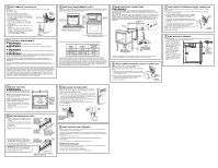
as a tag, to the service panel. Place oven on table or platform even with the cutout opening. For a single oven, the platform must support 200 lbs. (91 kg); and for a double oven, the platform must support 375 lbs. (170 kg). Connect the flexible conduit to the electrical junction box as shown - GE JTP70WMWW | Installation Instructions - Page 3
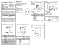
Hornos de pared eléctricos empotrados de 27" y 30" ¿Preguntas? Llame al 1.800.GE.CARES (1.800.432.2737) o Ubicación de la caja de conexiones Altura hasta la parte inferior de la caja de conexiones Ubicación recomendada de la abertura desde el piso Horno doble de 27" 27" (68,6 cm) 25" (63,5 cm) - GE JTP70WMWW | Installation Instructions - Page 4
piezas, llame al 1.800.GE.CARES. 6 CONEXIÓN DE CIRCUITO C. Quite el reborde. Para modelos de 27" (68,6 cm) con el reborde inferior la bisagra bien colocada en la parte inferior de la ranura de la Accione la energía del horno (consulte el Manual del propietario). Verifique que las unidades de
-
 1
1 -
 2
2 -
 3
3 -
 4
4
 |
 |
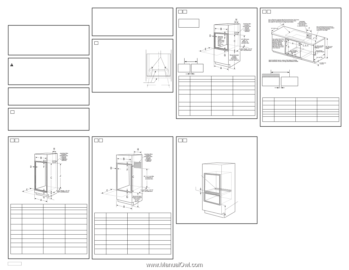
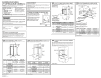
CUTOUT FOR SINGLE OVENS IN WALL CABINET
NOTE:
If the cabinet does not have a front frame and the sides are less than ¾” (1.9 cm) thick,
shim both sides equally to establish the cutout width.
A
2
BEFORE YOU BEGIN
Read these instructions completely and
carefully.
•
IMPORTANT —
Save these
instructions for local inspector’s use.
•
IMPORTANT —
Observe all
governing codes and ordinances.
•
Note to Installer –
Be sure to leave these
instructions with Consumer.
•
Note to Consumer –
Keep these
instructions for future reference.
•
Skill level –
Installation of this appliance
requires a qualified installer or electrician.
•
Proper installation is the responsibility
of the installer.
•
Product failure due to improper installation
is not covered under Warranty.
Installation Instructions
27
"
&
30
"
Electric Built-In Wall Ovens
31-10730-1
08-09
JR
FOR YOUR SAFETY:
WARNING
:
Before beginning the installation, switch power off at the service
panel and lock the service disconnecting means to prevent power from being switched on accidentally.
When the service disconnecting means cannot be locked, securely fasten a prominent warning device,
such as a tag, to the service panel.
Be sure the oven is securely installed in a cabinet that is firmly attached to the house structure.
Weight on the oven door could cause the oven to tip and result in injury. Never allow anyone to climb,
sit, stand or hang on the oven door.
Make sure the wall coverings, counters and cabinets around the oven can withstand the heat
(up to 200°F [93.3°C]) generated by the oven.
Questions?
Call 1.800.GE.CARES (1.800.432.2737) or visit www.GEAppliances.com
In Canada, call 1.800.561.3344 or visit www.GEAppliances.ca
MATERIALS YOU MAY NEED
Junction Box
Wire Nuts
Strain Relief Clamp for 1/2" Conduit
36" (91 cm) of String
TOOLS YOU MAY NEED
1/8" Drill Bit and Electric or Hand Drill
Phillips Screwdriver
Wire Strippers
REMOVE PACKAGING MATERIALS
Failure to remove packaging materials could result in damage to the appliance. Remove all
packing parts from oven, racks and heating elements. Remove protective film and labels on the
outer door and control panel. Also, remove plastic on trims and panel, all tape around the oven
and any shipping screws securing the oven to the base pad. Open oven door and remove
literature pack and oven racks. Remove the bottom trim from the top of the oven. It will be
installed at the end of the installation process. The trim is wrapped separately and taped
to the top of the unit.
1
PREPARE THE OPENING (FOR INDOOR USE ONLY)
NOTE:
If the cabinet does not have a solid bottom,
two braces or runners must be installed to support
the weight of the oven. For single ovens, the runners
and braces must support 200 lbs (91 kg). For double
ovens, the runners and braces must support 375 lbs.
(170 kg).
NOTE:
If marks, blemishes or the cutout opening are
visible above the installed oven, it may be necessary
to add wood shims under the runners and front trim
until the marks or opening are covered.
NOTE:
If the cabinet does not have a front frame
and the sides are less than ¾" (1.9 cm) thick, shim
both sides equally to establish the cutout width.
2
ATTENTION INSTALLER:
All electric wall ovens must be hard-wired (direct-wired)
into an approved junction box. A plug and receptacle is NOT permitted on these products.
These ovens are not
approved for stackable
installations.
Cutout –
observe all
dimensions and
requirements.
Cutout –
observe all
dimensions and
requirements.
2" (5.1 cm) Min.
30.5" (77.5 cm)
Center Line
Center Line
Side-by-Side Installations (30" only)
Install two ovens in separate cutouts.
Dimension
Dimension Description
27" Single Oven
30" Single Oven
A
Cabinet Width
27" (68.6 cm)
30" (76.2 cm)
B
Cutout Width
25" (63.5 cm) min.
28
1
⁄
2
" (72.4 cm) min.
25
1
⁄
4
" (64.1 cm) max.
28
5
⁄
8
" (72.7 cm) max.
C
Cutout Height
27
5
⁄
8
" (70.2 cm) min.
27
1
⁄
4
" (69.2 cm) min.
28
1
⁄
8
" (71.4 cm) max.
27
5
⁄
16
" (69.4 cm) max.
D
Overlap of Oven Over
1" (2.5 cm)
11
⁄
16
" (1.75 cm)
Side Edges of Cutout
E
Clearance to
20" (50.8 cm) min.
21" (53.3 cm) min.
Adjacent Corners,
Drawers, Walls, etc.,
When Door Is Open
F
Overlap of Oven
1" (2.5 cm) min.
1" (2.5 cm) min.
Top of Cutout
G
Overlap of Oven
1" (2.5 cm) min.
1
1
⁄
4
" (3.2 cm)
Bottom of Cutout
H
Junction Box Location
8
3
⁄
4
" (22.2 cm) max.
9
1
⁄
2
" (24.1 cm) max.
right side only
right side only
CUTOUT FOR DOUBLE OVENS
(with Upper Microwave Oven)
NOTE:
If the cabinet does not have a front frame and the sides are less than ¾" (1.9 cm) thick,
shim both sides equally to establish the cutout width.
D
2
Dimension
27" Oven
30" Oven
Dimension
Description
with Microwave
with Microwave
A
Cabinet Width
27" (68.6 cm)
30" (76.2 cm)
B
Cutout Width
25" (63.5 cm) min.
28
1
⁄
2
" (72.4 cm) min.
25
1
⁄
4
" (64.1 cm) max.
28
5
⁄
8
" (72.7 cm) max.
C
Cutout Height
41
1
⁄
8
" (104.5 cm) min.
42
3
⁄
16
" (107.2 cm) min.
41
1
⁄
4
" (104.8 cm) max.
42
1
⁄
4
" (107.3 cm) max.
D
Overlap of Oven
1" (2.5 cm)
11
⁄
16
" (1.75 cm)
Over Side Edges
of Cutout
E
Clearance to Adjacent
20" (50.8 cm) min.
21" (53.3 cm)
Corners, Drawers, Walls,
etc., When Door Is Open
F
Overlap of Oven
1" (2.5 cm) min.
1" (2.5 cm) min.
Top of Cutout
G
Overlap of Oven
1" (2.5 cm) min.
1
1
⁄
4
" (3.2 cm)
Bottom of Cutout
H
Junction Box Location
8
3
⁄
4
" (22.2 cm) max.
9
1
⁄
2
" (24.1 cm) max.
right side only
right side only
Continue to Section 3.
Suitable
Bracing
to Support
Runners
C
L
21 5/8"
(54.9 cm) Over
Centerline
of Cabinet
2" x 4" (5 cm x 10 cm)
or Equivalent Runners Level
with Bottom of Cutout
CUTOUT FOR SINGLE OVENS – UNDER COUNTER
NOTE:
These ovens are only approved to be installed under the specific models as labeled on
the unit.
B
2
Dimension
Dimension Description
27" Single Oven
30" Single Oven
A
Cabinet Width
25" (63.5 cm) min.
28
1
⁄
2
" (72.4 cm) min.
25
1
⁄
4
" (64.1 cm) max.
28
5
⁄
8
" (72.7 cm) max.
B
Cutout Height
27
5
⁄
8
" (70.2 cm) min.
27
1
⁄
4
" (69.2 cm) min.
28
1
⁄
8
" (71.4 cm) max.
27
5
⁄
16
" (69.4 cm) max.
C
Unit Overlap Top
1" (2.5 cm)
1" (2.5 cm)
D
Unit Overlap Bottom
1" (2.5 cm)
1
1
⁄
4
" (3.2 cm)
E
Unit Overlap Side Edges
1" (2.5 cm)
11
⁄
16
" (1.75 cm)
F
Junction Box Location
8
3
⁄
4
" (22.2 cm) max.
9
1
⁄
2
" (24.1 cm) max.
right side only
right side only
Continue to Section 3.
NOTE:
One cooktop may be centered over either
oven in the side-by-side installation.
Cutout – observe
all dimensions and
requirements.
2" (5.1 cm) Min.
30.5" (77.5 cm)
Center Line
Center Line
Side-by-Side Installations (30" only)
Install two ovens in separate cutouts.
Cooktop
Cutout – observe
all dimensions and
requirements.
CUTOUT FOR INSTALLATION OVER A WARMING
DRAWER
NOTE:
Install the oven only with specific models listed on the label located on top of the oven.
NOTE:
Additional clearances between cutouts may be required. Check to be sure the oven
supports above the Warming Drawer location do not obstruct the required interior depth and
height.
When installing a Warming Drawer below a single or double oven, a separate 120V, 60 HZ,
properly grounded receptacle must be installed. Refer to installation instructions packed with
the Warming Drawer for specific installation requirements.
E
2
Anti-Tip Block Against
Rear Wall Per Warming
Drawer Requirement
2" (5.1 cm)
Min.
Per Warming
Drawer
Requirement
Continue to Section 3.
DESIGN INFORMATION
SINGLE OVEN INSTALLATIONS
The single oven may be installed in a cabinet alone or above a warming drawer. The single oven may
also be installed below a countertop or below specified cooktops. See the label on top of the oven for
approved models.
DOUBLE OVEN INSTALLATIONS
A double oven may be installed in a cabinet alone or above a warming drawer. See the label on top of
the oven for approved models.
IMPORTANT:
Always refer to individual installation instructions packed with each product for specific
requirements.
CUTOUT FOR DOUBLE OVENS
(2 Thermal Ovens)
NOTE:
If the cabinet does not have a front frame and the sides are less than ¾” (1.9 cm) thick,
shim both sides equally to establish the cutout width.
C
2
Dimension
Dimension Description
27" Double Oven
30" Double Oven
A
Cabinet Width
27" (68.6 cm)
30" (76.2 cm)
B
Cutout Width
25" (63.5 cm) min.
28
1
⁄
2
" (72.4 cm) min.
25
1
⁄
4
" (64.1 cm) max.
28
5
⁄
8
" (72.7 cm) max.
C
Cutout Height
49
11
⁄
16
" (126.2 cm) min.
51
13
⁄
16
" (131.6 cm) min.
50
1
⁄
8
" (127.3 cm) max.
51
15
⁄
16
" (131.9 cm) max.
D
Overlap of Oven
1" (2.5 cm)
11
⁄
16
" (1.75 cm)
Over Side Edges
of Cutout
E
Clearance to Adjacent
20" (50.8 cm) min.
21" (53.3 cm) min.
Corners, Drawers, Walls,
etc., When Door Is Open
F
Overlap of Oven
1" (2.5 cm) min.
1" (2.5 cm) min.
Top of Cutout
G
Overlap of Oven
1" (2.5 cm) min.
1
1
⁄
4
" (3.2 cm)
Bottom of Cutout
H
Junction Box Location
8
3
⁄
4
" (22.2 cm) max.
9
1
⁄
2
" (24.1 cm) max.
right side only
right side only
J
Height to Bottom of
44" (111.8 cm)
47" (119.4 cm)
Junction Box
K
Recommended
13
1
⁄
4
" (33.7 cm)
12" (30.5 cm)
Cutout Location from
Floor
Continue to Section 3.